Oxygen-enriched combustion method and device
An oxygen-enriched combustion and oxygen technology, applied in the field of combustion, can solve the problems of affecting the economic benefits of production and operation, increasing the labor intensity of operators, and insufficient combustion, so as to avoid coking at the burner outlet, avoid black smoke from the chimney, and improve combustion quality effect
- Summary
- Abstract
- Description
- Claims
- Application Information
AI Technical Summary
Problems solved by technology
Method used
Image
Examples
Embodiment 1
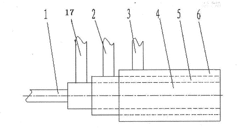
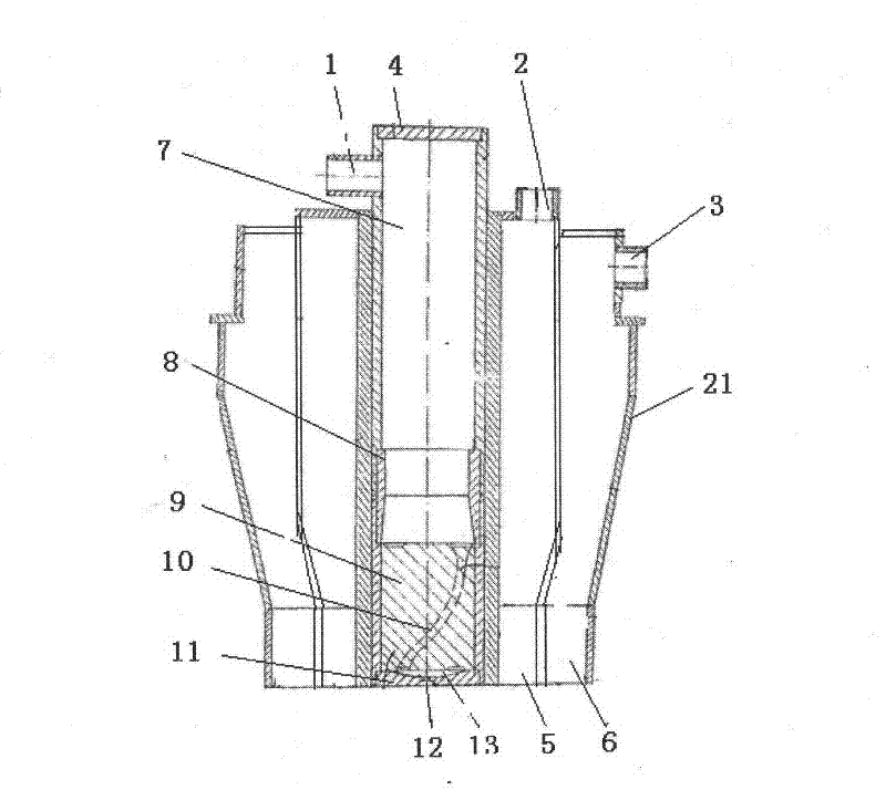
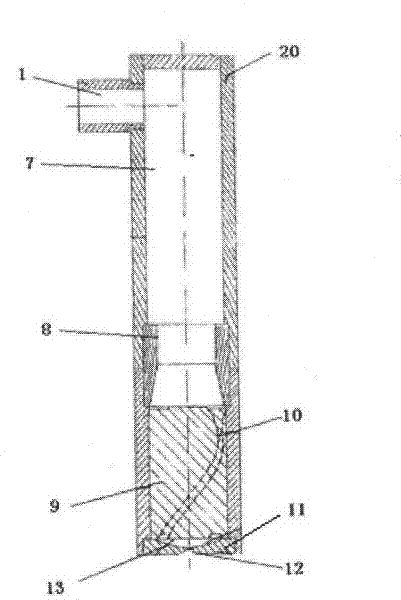
[0021] Oxygen-enriched combustion device of the present invention such as figure 1 , figure 2 , image 3 As shown, it includes a casing 21 , a fuel nozzle 4 , an oxygen nozzle 5 and an air nozzle 6 . The oxygen nozzle, the air nozzle and the fuel nozzle are arranged in a concentric ring, the fuel nozzle is located at the center, the air nozzle is located at the periphery, and the oxygen nozzle is located between the fuel nozzle and the air nozzle. The air nozzle is connected to the blower through the air inlet pipe 3, the air line. The oxygen nozzle is connected to the pressure swing adsorption oxygen generator through the oxygen inlet pipe 2 and the oxygen pipeline. The pressure swing adsorption oxygen generator is mainly composed of a blower, a vacuum pump, a switching valve, an adsorber and an oxygen balance tank. The fuel nozzle is a swirl type liquid fuel burner, which is composed of a housing 20 , a liquid swirl nozzle assembly 11 , a swirl channel cylinder 9 , a con...
Embodiment 2
[0024] Another embodiment of the present invention is as Figure 4 As shown, the fuel burner is a swirl gas fuel nozzle, which is composed of a housing 20 , a gas swirl nozzle assembly 16 , a swirl gas channel column 18 , a connecting piece 8 and a high-pressure gas fuel chamber 14 . The gas swirl nozzle assembly, the swirl gas channel column, the connecting piece and the high-pressure gas fuel chamber are connected in sequence, the high-pressure gas fuel chamber is connected to the gas fuel inlet pipe 17, and is connected to the fuel supply equipment through the gas fuel inlet pipe and the gas fuel pipeline . There are 10 swirl gas channels 19 in the swirl channel column, and the gas swirl nozzle assembly is provided with 10 gas fuel nozzles 15, which correspond to the swirl gas channels and are evenly distributed around the center of the fuel burner. The gas fuel nozzle is a diffusion nozzle. Other structures and combustion modes are the same as in Example 1.
Embodiment 3
[0026] Another embodiment of the present invention is as Figure 5 As shown, the fuel burner is a swirling gas-liquid dual-purpose fuel nozzle. The swirling gas-liquid dual-purpose fuel nozzle is composed of a liquid fuel part and a gas fuel part, the liquid fuel part is located at the center, and the gas fuel part is ring-shaped and located around the liquid fuel part. The liquid fuel part is composed of a liquid swirl nozzle assembly 11, a swirl channel cylinder 9, a connecting piece 8 and a high-pressure liquid fuel chamber 7, which are sequentially connected. The high-pressure liquid fuel chamber is connected to the liquid fuel through the liquid fuel inlet pipe 1, the liquid fuel pipeline Tank connection. Five swirl channels 10 are arranged in the swirl channel cylinder 9, a swirl chamber 13 is arranged between the liquid swirl nozzle assembly and the swirl channel cylinder, and a liquid fuel nozzle 12 is arranged at the center of the liquid swirl nozzle assembly, The l...
PUM
 Abstract
Description
Claims
Application Information
 - R&D
- Intellectual Property
- Life Sciences
- Materials
- Tech Scout
- Unparalleled Data Quality
- Higher Quality Content
- 60% Fewer Hallucinations
Browse by: Latest US Patents, China's latest patents, Technical Efficacy Thesaurus, Application Domain, Technology Topic, Popular Technical Reports.
© 2025 PatSnap. All rights reserved.Legal|Privacy policy|Modern Slavery Act Transparency Statement|Sitemap|About US| Contact US: help@patsnap.com


