
Gas sealing experimental device and method

An experimental device and gas sealing technology, which can be applied to electromagnetic measurement devices, liquid/vacuum measurement for liquid tightness, and measurement of fluid acceleration and deceleration rates. Affect the sensitivity of the sensor, the error of the measurement result, etc., to achieve the effect of simple and easy measurement method, high measurement accuracy and wide application range

Active Publication Date: 2012-06-20
海宁市黄湾镇资产经营有限公司
View PDF4 Cites 25 Cited by
  • Summary
  • Abstract
  • Description
  • Claims
  • Application Information

AI Technical Summary

Problems solved by technology

Since the object of the eddy current sensor must be a metal conductor, this greatly limits the measurement of the gas film thickness of the sealing end face of non-metallic materials. At the same time, the area of ​​the measured surface should be greater than 1.83 times the diameter of the eddy current sensor. When the sealing ring is narrow Its use is also restricted
At present, the common installation method of eddy current sensor is to drill a hole on the static ring, and install the eddy current sensor in the hole. If the hole is drilled, it will affect the working state of the end face. If the hole is blind, the distance between the eddy current sensor and the end face of the moving ring will be affected. The sealing ring material will greatly affect the sensitivity of the sensor
In addition, because there is a certain circumferential waviness on the sealing surface, this installation method will cause the measurement results to include circumferential waviness. The thickness of the gas film on the end surface is on the order of microns and the surface roughness is the same order of magnitude, and the surface waviness is greater than the roughness. Therefore, the measurement results There is a large error

Method used


Image

  • Gas sealing experimental device and method
  • Gas sealing experimental device and method
  • Gas sealing experimental device and method

Examples


Embodiment Construction

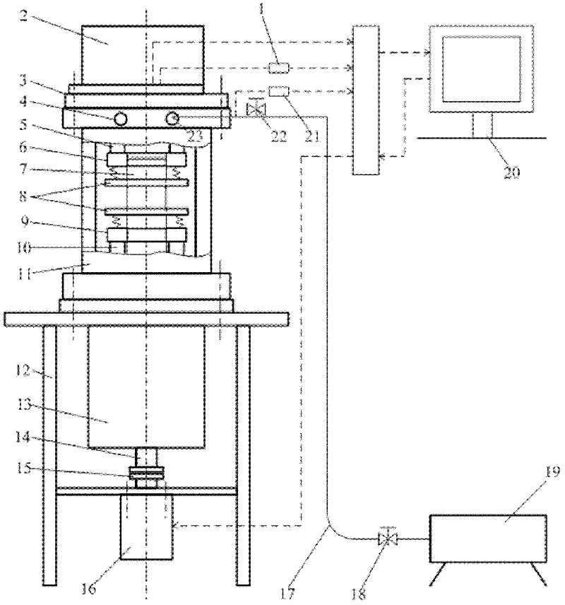
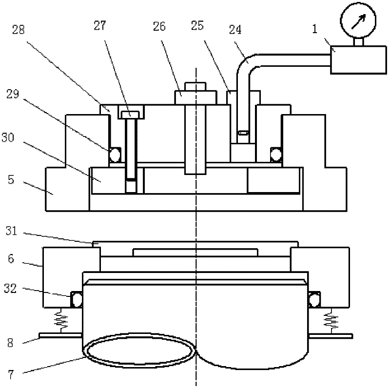
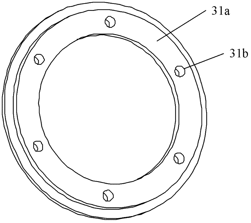
[0031] refer to figure 1 , figure 2 , image 3 and Figure 4 , the gas-tight experimental device of the present invention includes a sealed chamber 11, a drive system, a gas supply circuit and a test system, and is characterized in that the sealed chamber 11 is vertically fixed on the bracket 12 by screws, and the sealed chamber 11 includes a The upper part of the experimental seal and the auxiliary seal located at the lower part of the sealing chamber, the experimental seal dynamic ring 6 and the auxiliary seal dynamic ring 9 are installed on the dynamic ring seat 8, and the dynamic ring seat 8 is fixed on the shaft sleeve 7 by set screws, and the experimental seal An O-shaped sealing ring 32 is installed between the moving ring 6 and the shaft sleeve 7. The experimental sealing static ring 5 is connected with the end cover 3 through pins, and the end cover 3 is connected with the sealing chamber 11 through screws. The auxiliary sealing static ring 10 Connected together w...


PUM


Abstract

The invention discloses a gas sealing experimental device which comprises a sealed cavity, a driving system, a gas supply loop and a test system. The gas sealing experimental device is characterized in that the sealed cavity is vertically fixed on a bracket by a bolt; the driving system comprises a motor, a coupler, a bearing box and a spindle; the motor is fixed on the bracket by the bolt; the motor and the spindle are connected by the coupler; the gas supply loop comprises a compressor, a pneumatic pipe and a pressure regulation valve; the compressor is connected with a gas inlet of the sealed cavity through the pneumatic pipe; and the test system comprises an eddy current sensor, a moving ring positioning sheet, a flowmeter and a pressure sensor. Through adoption of the gas sealing experimental device, the sealed end surface gas leakage rate and the gas film thickness of various gas end surfaces can be measured on line. The measurement method of gas leakage rate is simple and easy to implement and has good dynamic response, the measurement of gas film thickness is not affected by the material of a seal ring, end surface width and the annular surface waviness of the seal ring, and revolving speed and pressure in the experiment process are adjustable.

Description

technical field [0001] The invention relates to the technical field of gas end face mechanical sealing experiments, in particular to a sealing experimental device and method for detecting the end face gas leakage rate and gas film thickness of various gas end face seals. Background technique [0002] Mechanical seals are the main means to prevent the shaft end leakage of rotary fluid machinery. Among them, dry gas end face seals are widely used in petrochemical, natural gas and other industries due to their outstanding advantages such as low power consumption, long working life, small leakage or even zero leakage. More and more widely, it is the preferred form of shaft end seal for rotary fluid machinery such as large compressors and special medium pumps, and it is also more and more widely used in reactors. [0003] With the wide application of dry gas seals, it is particularly important to form a unified optimal design criterion for dry gas seals. The blind area of ​​desi...

Claims


Application Information

Patent Timeline
IPC IPC(8): G01M3/26G01B7/06
Inventor 白少先柏林清彭旭东孟祥铠李纪云盛颂恩
Owner 海宁市黄湾镇资产经营有限公司
Learn More