Sample cup and multi-channel optical test system containing same

A sample cup and sample technology, applied in the field of sample cups, can solve the problems of low heat conduction efficiency, cumbersome procedures, and affecting the accuracy of experimental results, etc.

Inactive Publication Date: 2012-06-20
BEIJING GENOME BIOTECH
View PDF6 Cites 5 Cited by
  • Summary
  • Abstract
  • Description
  • Claims
  • Application Information

AI Technical Summary

Problems solved by technology

[0009] First of all, after the sample is added to the reaction chamber 10, there will usually be air bubbles in the reaction chamber 10, and a centrifuge must be used to remove the air bubbles, and the process is very cumbersome.
Even if a centrifuge was used to remove air bubbles at the beginning of the experiment, the sample in the reaction chamber 10 often generates air bubbles during the heating and cooling process. Since the sample cup 2 needs to be sealed with a sealing cover 12 during the experiment, this Once the air bubbles are generated, since the air bubbles have nowhere to go, they will inevitably stay randomly in the reaction chamber 10, which may cause inaccurate photometry in severe cases and affect the accuracy of the experimental results.
[0010] Secondly, although the light excitation module 46 and the light detection module 48 are used for optical observation of the samples in the reaction chamber 10 during the experiment, the natural light (also called stray light) in the environment will inevitably pass through the first wall 32A. Into the reaction chamber 10, in other words, stray light enters the sample optical path, thereby affecting the accuracy of the measurement
[0011] In addition, the materials commonly used for the flexible wall 18 are polypropylene, polyethylene, polyester, and other polymers, which are not only uneconomical, but also have low heat transfer efficiency.

Method used


Image

  • Sample cup and multi-channel optical test system containing same
  • Sample cup and multi-channel optical test system containing same
  • Sample cup and multi-channel optical test system containing same

Examples


Embodiment Construction

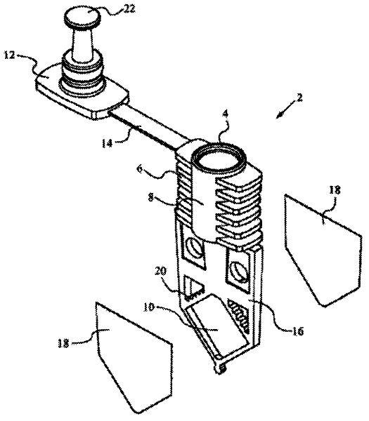
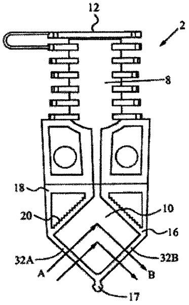
[0030] Referring to FIGS. 4-8 , the sample cup of the present invention includes a sealing cover 1 , a flexible connecting plate 2 , a cup body 12 and a sample cavity patch 11 . When the sample cup is working, the sample stored in the sample chamber 7 of the sample cup will experience a continuous heating process, and the pressure in the cup will constantly change alternately, and the sealing cover 1 is made of flexible material. When the pressure in the cup increases When it is large, the flexible sealing cover 1 can be deformed and expanded, so as to avoid inaccurate measurement results caused by overflow of samples.

[0031] The flexible connecting plate 2 connects the sealing cover 1 and the cup body 12 together, so that the sealing cover 1 will not break away from the cup body 12, avoiding confusion between the sealing covers of multiple sample cups, thereby avoiding confusion due to the sealing cover 1 resulting in cross-contamination of samples.

[0032] The cup body 1...


PUM

PropertyMeasurementUnit
angleaaaaaaaaaa

Abstract

The invention provides a sample cup and a multi-channel optical test system containing the same. The sample cup comprises a sealing cover, a flexible connection plate, a cup body and a sample container patch, wherein a sample containing cavity is arranged at the lower part of the cup body and is used for containing a sample; a vertical sample injection inlet part, a main sample injection channel and an air exhaust channel are arranged at the upper part of the cup body; a boundary surface between the sample injection inlet part and the cup body below the sample injection inlet part is an inclined plane; the upper ports of the main sample injection channel and the air exhaust channel are positioned at the upper and lower sides of the inclined plane; the upper port of the air exhaust channel is positioned above the inclined plane and is higher than that of the main sample injection channel; the upper part of the air exhaust channel vertically extend downward from the upper port and is roughly parallel to the sample injection inlet part and the main sample injection channel; the lower parts of the air exhaust channel and the main sample injection channel are inward bent; the lower ports of the air exhaust channel and the main sample injection channel are converged at the highest point of the sample containing cavity; and the cross-sectional area of the sample injection inlet part is equal to the sum of the cross-sectional areas of the main sample injection channel and the air exhaust channel. Through arranging the air exhaust channel, air bubbles generated in a sample injection process or an experiment process can be smoothly discharged to be above the sample, thereby not influencing the measurement precision at all.

Description

technical field [0001] The present invention relates to a sample cup, more specifically, to a sample cup used in a multi-channel optical testing system. Background technique [0002] Nucleic acid amplification reactions are critical for many research, medical, and industrial applications. These reactions are used in clinical and biological research, detection and monitoring of infectious diseases, detection of mutations, detection of cancer markers, environmental monitoring, genetic identification, detection of pathogens in biodefense applications, and more. In particular, the polymerase chain reaction (PCR) has been used in all of these areas, including applications to virus and bacteria detection, viral load monitoring, detection of rare and / or difficult-to-culture pathogens, rapid detection of bioterror threats, cancer Testing for minimal residual disease in patients, food pathogen testing, blood supply screening, and more. With regard to PCR, the main reasons for its w...

Claims


Application Information

Patent Timeline
Patent Type & Authority Applications(China)
IPC IPC(8): G01N21/03
Inventor 张洪刚朱福来孙宏伟苑红丽陈启跃陈剑飞
Owner BEIJING GENOME BIOTECH
Why Eureka
Try Eureka