System and method for monitoring gas pollution based on passive long-path differential absorption spectrum technology

A technology of differential absorption spectrum and gas pollution, applied in the measurement of color/spectral characteristics, etc., can solve the problems of complex structure, high power consumption, low life of artificial light source, etc., to achieve the effect of simple system structure and error resolution

Inactive Publication Date: 2012-06-20
ANHUI INST OF OPTICS & FINE MECHANICS - CHINESE ACAD OF SCI
View PDF2 Cites 12 Cited by
  • Summary
  • Abstract
  • Description
  • Claims
  • Application Information

AI Technical Summary

Problems solved by technology

The advantages of passive multi-axis differential absorption spectroscopy technology are simple structure and low power consumption; the disadvantages are that the observation direction of the instrument is required to be free of buildings, and there are restrictions on the selection of installation locations.
Long-range differential absorption spectroscopy technology can quickly monitor the change of gas concentration in the optical path through the emission and reception of the light source, but the structure of the emission and reception device of the light source is complex; the matching corner reflector is inconvenient to install; the artificial light source used has a low service life, high power consumption

Method used


Image

  • System and method for monitoring gas pollution based on passive long-path differential absorption spectrum technology
  • System and method for monitoring gas pollution based on passive long-path differential absorption spectrum technology

Examples


Embodiment Construction

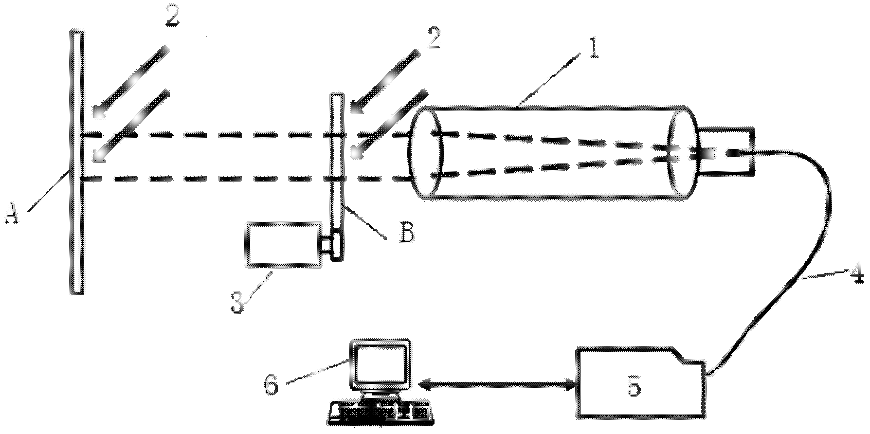
[0011] Such as figure 1 As shown, the distance between diffuse reflector A and receiving telescope 1 is 100-400m, the distance between diffuse reflector B and receiving telescope 1 is 0.2m, adjust diffuse reflector B to be parallel to diffuse reflector A, adjust receiving telescope 1, Diffuse reflector A is observed. When measuring the reference spectrum, the motor 3 is controlled to rotate, the diffuse reflector B is cut into the optical path, the receiving telescope 1 collects the sunlight 2 reflected by the diffuse reflector B, and is transmitted to the spectrometer 5 through the optical fiber 4; when the atmospheric spectrum is measured, the motor 3 is controlled to rotate, The diffuse reflection plate B is cut out of the optical path, and the sunlight 2 reflected by the diffuse reflection plate A is collected by the receiving telescope 1 and transmitted to the spectrometer 5 through the optical fiber 4 . The scattered light entering the spectrometer 5 is transmitted to t...


PUM


Abstract

The invention discloses a system and a method for monitoring gas pollution based on the passive long-path differential absorption spectrum technology. The system adopts the technical scheme that a receiving telescope is arranged; a diffuse reflection board A is installed right ahead the receiving telescope; a diffuse reflection board B is installed between the receiving telescope and the diffuse reflection board A; the diffuse reflection boards A and B are parallel; and a rotating shaft is connected with the lower end of a baseplate of the diffuse reflection board B. A control motor rotates, and the diffuse reflection board B is cut in and cut out of a receiving optical path of the receiving telescope; the sunlight which is reflected by the diffuse reflection boards A and B is collected by the receiving telescope, and is transmitted to a spectrometer through optical fibers respectively; scattered light entering the spectrometer is subjected to chromatic dispersion, photoelectric conversion and digitization, transferred to a computer through an USB cable for storage; and the concentration of the pollution gas can be analyzed and calculated through utilizing the differential absorption spectrum method. Through the combination of the advantages of the conventional active and passive differential absorption spectrum technologies, the system structure is simple, and the deficiencies that in the system for monitoring gas pollution based on the active long-path differential absorption spectrum technology of the prior art, the artificial light source has short service life and high power consumption and the angle reflecting mirror is difficult to install are overcome.

Description

technical field [0001] The invention belongs to the technical field of environmental monitoring, in particular to a passive long-range differential absorption spectrum gas pollution monitoring system and method for atmospheric environment monitoring based on solar astigmatism. Background technique [0002] The existing differential absorption spectroscopy technology for monitoring gas pollution can be divided according to different light sources: passive multi-axis differential absorption spectroscopy technology using the scattered light of the sun; long-range differential absorption spectroscopy technology using artificial light sources such as xenon lamps and LEDs. The advantages of passive multi-axis differential absorption spectroscopy technology are simple structure and low power consumption; the disadvantages are that the observation direction of the instrument is required to be free of buildings, and there are restrictions on the selection of installation locations. ....

Claims


Application Information

Patent Timeline
Patent Type & Authority Applications(China)
IPC IPC(8): G01N21/31
Inventor 周海金刘文清司福祺刘进窦科
Owner ANHUI INST OF OPTICS & FINE MECHANICS - CHINESE ACAD OF SCI
Why Eureka
Try Eureka