Non-contact real-time physiological signal monitoring system

A physiological signal, non-contact technology, applied in the field of physiological signal detection in the medical industry, can solve problems such as difficult algorithm processing, radar receiving interference, and poor real-time performance of the algorithm, so as to improve the recognition effect, expand the spatial range, and reduce environmental noise.

Inactive Publication Date: 2012-06-20
INST OF MICROELECTRONICS CHINESE ACAD OF SCI
View PDF12 Cites 30 Cited by
  • Summary
  • Abstract
  • Description
  • Claims
  • Application Information

AI Technical Summary

Problems solved by technology

[0006] 1. In order to monitor the target within a certain distance and space range, a large radiation power is required, and the working efficiency of the monitoring device is low
When using biological radar to monitor the physiological parameters of the human body, it is necessary to radiate electromagnetic waves of sufficient intensity to the human body so that the attenuated electromagnetic waves after reflection can still be detected, and in order to function within a certain distance and space, high power is often required Radiation sources that irradiate a large area of ​​space (omnidirectional radiation or half-space radiation, etc.), which is not conducive to saving power consumption, will increase electromagnetic pollution, and may cause the monitoring target to receive unnecessary strong radiation
In addition, in order to make the irradiation area contain more space, it is necessary to use an omnidirectional antenna or a bulky antenna, which is not conducive to the integration of the antenna;
[0007] 2. It is difficult to distinguish between monitoring targets and o

Method used


Image

  • Non-contact real-time physiological signal monitoring system
  • Non-contact real-time physiological signal monitoring system
  • Non-contact real-time physiological signal monitoring system

Examples


Example Embodiment

[0021] In order to make the objectives, technical solutions, and advantages of the present invention clearer, the following further describes the present invention in detail with reference to specific embodiments and drawings.

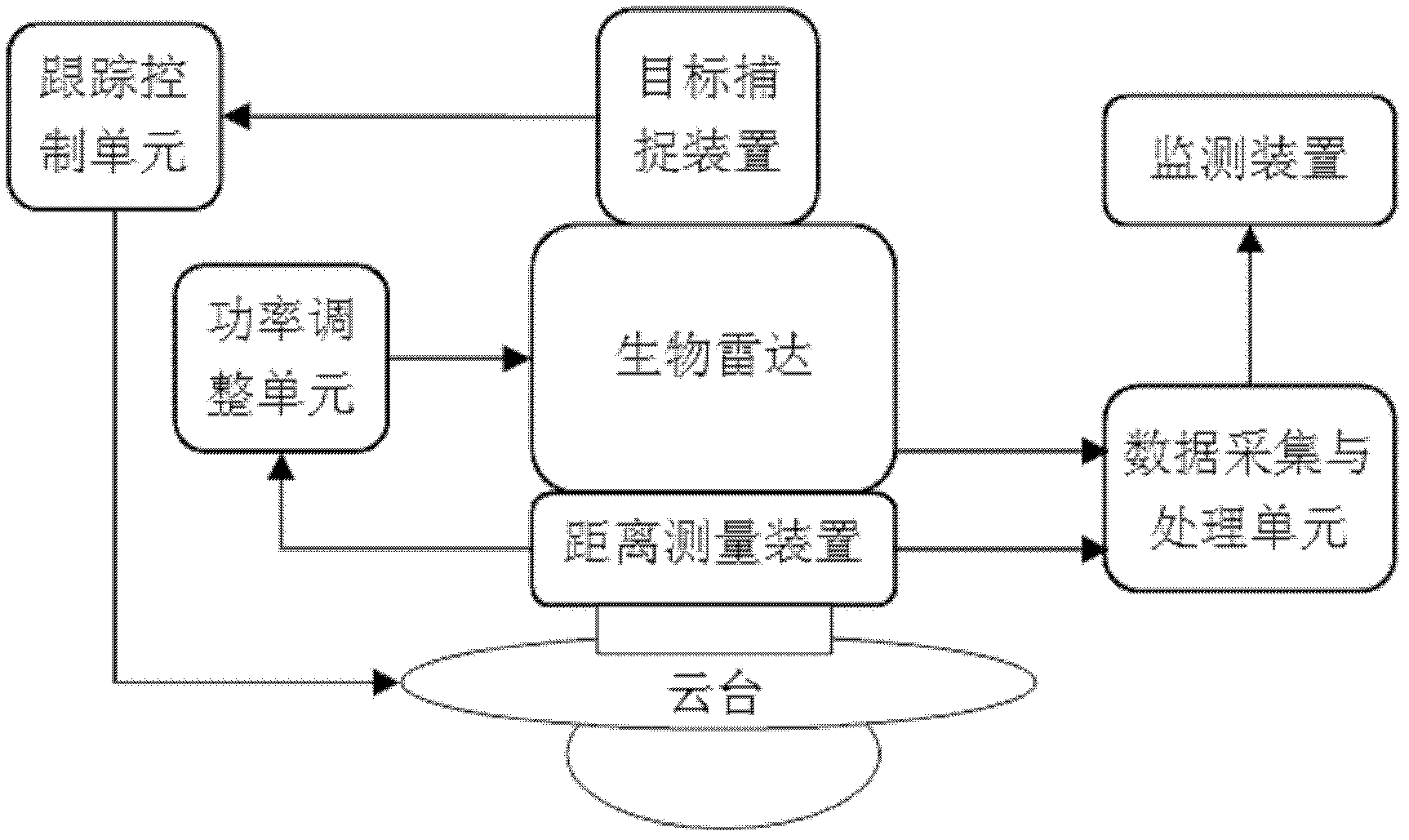
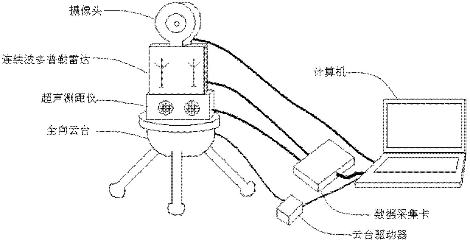
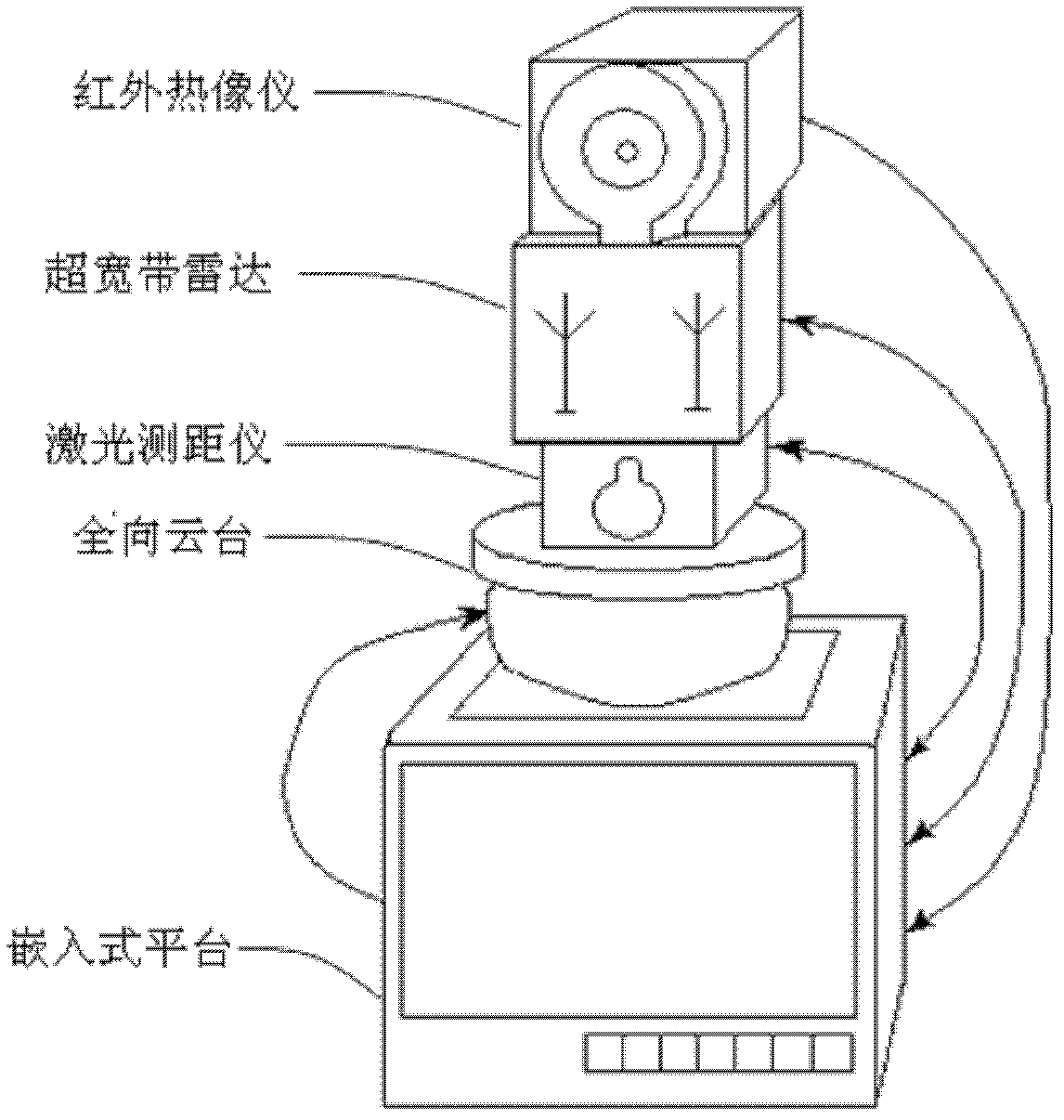
[0022] The purpose of the present invention is to provide a non-contact real-time physiological monitoring device with low power, high directivity and large monitoring range. The device can automatically capture the target to be monitored by the bio-radar, make the highly directional antenna always aim at the monitoring target, and can automatically obtain the distance information from the target, automatically adjust the radar power according to the distance information, and optimize the radar signal processing algorithm to achieve The purpose of monitoring target positioning is accurate, low electromagnetic radiation power, and large monitoring range.

[0023] figure 1 It is a schematic diagram of a non-contact real-time physiological signal monitoring de...


PUM


Abstract

The invention discloses a non-contact real-time physiological signal monitoring system, which comprises a target capturing device, a tracking control unit, a biologic radar and a data acquiring and processing unit, wherein the target capturing device is used for capturing a target to obtain position information of the target; the tracking control unit is used for controlling rotation and/or pitching of a holder according to the position information of the target and making the antenna of the biologic radar above the holder align the target; the biologic radar is used for generating and transmitting a detection signal and receiving an echo signal which is reflected by the target and carries human physiological information; and the data acquiring and processing unit is used for sampling the echo signal of the biologic radar and analyzing and extracting the physiological information of the detected target from a sampled signal. In the system, a target capturing and tracking unit can ensure that the antenna of a physiological signal sensor always points at the target, so that the space range of the detected target can be expanded conveniently and the required radiant power is low.

Description

technical field [0001] The invention relates to the field of physiological signal detection in the medical industry, in particular to a non-contact real-time physiological signal monitoring system. Background technique [0002] Real-time monitoring of human physiological parameters is of great significance in many occasions, such as clinically understanding the patient's respiratory and heart rate changes over time, family health monitoring of the elderly, and physiological status monitoring of special populations. In order to make real-time monitoring more convenient and have as little impact on the monitored objects as possible, at present, the volume and power consumption of physiological signal acquisition systems are greatly reduced, portability and wearability are enhanced, and non-contact Physiological signal monitoring method. [0003] In non-contact physiological signal monitoring, the sensor or probe used for physiological signal acquisition is not in contact with...

Claims


Application Information

Patent Timeline
IPC IPC(8): G01S17/88G01S7/497A61B5/00
Inventor 胡巍王云峰张海英
Owner INST OF MICROELECTRONICS CHINESE ACAD OF SCI
Why Eureka
Try Eureka