System for automatically monitoring state of base station antennae

An automatic monitoring system, a technology for base station antennas, applied to antennas, electrical components, etc., can solve the problems of heavy workload, poor work safety, long discovery cycle, etc., and achieve timely and accurate control and adjustment, low labor intensity, and high work efficiency. Effect

Active Publication Date: 2012-06-20
盐城博思维信息科技有限公司
View PDF3 Cites 21 Cited by
  • Summary
  • Abstract
  • Description
  • Claims
  • Application Information

AI Technical Summary

Problems solved by technology

[0003] 1. Relying on manual measurement methods cannot accurately grasp the status data of mobile communication antennas in real time, and cannot provide timely and accurate basic data for wireless network planning and optimization;
[0004] 2. The problem discovery cycle is long
The state parameters of the mobile communication antenna need manual on-site measurement, and the failure or abnormal change of the mobile communication antenna due to theft, man-made sabotage, illegal operation and other unexpected reasons such as strong wind, hail, impact, etc. cannot be found in the first place;
[0005] 3. It takes a long time to deal with problems required by measurement or adjustment, and the efficiency is low. Especially in the actual production process, it is difficult to meet the needs of special scene work, such as high mountain stations and remote area stations. The round trip time is long and the cost-efficiency ratio is poor. ; Some mobile communication base stations are located in residential ar

Method used


Image

  • System for automatically monitoring state of base station antennae
  • System for automatically monitoring state of base station antennae
  • System for automatically monitoring state of base station antennae

Examples


Embodiment 1

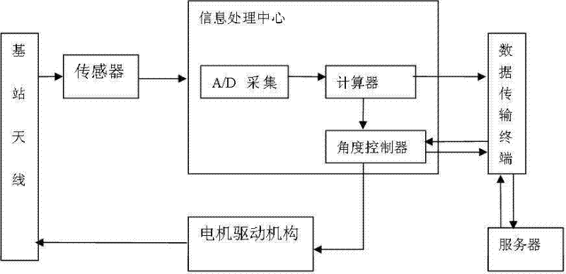
[0025] On antenna 1, first transmit the real-time data of antenna 1 (including antenna azimuth, pitch angle, roll angle data, altitude data, etc.) to sampler 2, and perform related A / D sampling. After sampling, The calculation part 3 is used to calculate the angle compensation, and the calculated data directly enters the angle controller 5, and the motor drive mechanism 6 drives the angle of the antenna 1 to make relevant real-time compensation.

Embodiment 2

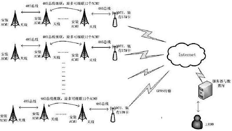
[0027] On antenna 1, first transmit the real-time data of antenna 1 (including antenna azimuth, pitch angle, and roll angle data) to sampler 2, and perform related A / D sampling. After sampling, use the calculation part 3 Carry out angle compensation calculation, the calculated data is transmitted through the GPRS transmission part 4 and enters the remote angle controller 5, and then the remote angle controller 5 controls the driving motor 6 to drive the angle of the antenna 1 to make relevant real-time compensation.

Embodiment 3

[0029] On antenna 1, first transmit the real-time data of antenna 1 (including antenna azimuth, pitch angle, and roll angle data) to sampler 2, and perform related A / D sampling. After sampling, use the calculation part 3 Carry out the angle compensation calculation, the data after the calculation enters the server remote monitoring center 7 after being transmitted by the GPRS transmission part 4, carries out the record of the real-time data of relevant data by the remote monitoring center 7, and counts in the distributed database 8, and in the database The historical data is compared, and the comparison result is fed back to the engineering end through other data interface 9.

[0030] About sensors in antenna status detection and control:

[0031] The detection of the azimuth is based on the magnetic induction type and MEMS acceleration sensor, which is composed of three sets of magnetic induction elements orthogonal to each other. One of the magnetic induction elements in the...


PUM


Abstract

The invention discloses a system for automatically monitoring the states of base station antennae. The system is characterized by comprising an antenna measurement control unit, a data transmission terminal and a server, wherein the antenna measurement control unit comprises sensors of all the antennae, a signal processing center and a motor driving mechanism; the data transmission terminal is provided with an SIM (subscriber identity module) card for identifying the antenna measurement control unit and is used for packaging acquired state data of each base station antenna, transmitting the packaged state data to the server through a GPRS (general packet radio service) channel, and simultaneously transmitting an antenna tuning command sent by a server side to the corresponding base station antenna measurement control unit to remotely control and adjust the antennae; and the server is used as a base station antenna monitoring terminal and a data base terminal, is provided with a data base and monitoring software, has a GPRS function, and can be used for receiving and transmitting GPRS data, and communicating with the data transmission terminal through the internet and the GPRS channel. The system disclosed by the invention can be used for automatically monitoring and controlling the base station antennae.

Description

technical field [0001] The invention relates to a system for automatically detecting, controlling and adjusting the state of an antenna. Background technique [0002] The antenna state of a mobile communication base station is an important engineering parameter in mobile communication, which basically determines the coverage of wireless signals. Therefore, it is necessary to design reasonable antenna state parameters in network planning, accurately implement according to the planning scheme in engineering construction, measure regularly in daily maintenance, and adjust as needed in network optimization. At present, the measurement and adjustment of the azimuth angle and pitch angle of the base station antenna status parameters by domestic communication operators only rely on manual methods. Measure with the horizontal ruler and compass; if the angle needs to be changed, it is implemented by loosening the screws and re-tightening the screws. On the other hand, the roll angl...

Claims


Application Information

Patent Timeline
IPC IPC(8): H01Q3/02H01Q3/08
Inventor 柳卫国吴迪王念朱翔肖斗王琪曾立芬石宇胡锐阳
Owner 盐城博思维信息科技有限公司
Why Eureka
Try Eureka