Self-heating floor and electrothermal component thereof

An electric heating and component technology, applied in the field of architectural decoration, can solve the problems of damaged electric heating wires, failure to implement, and potential safety hazards

Inactive Publication Date: 2013-07-17
葛林
View PDF10 Cites 0 Cited by
  • Summary
  • Abstract
  • Description
  • Claims
  • Application Information

AI Technical Summary

Problems solved by technology

Although this document does not describe how to wire the heating wires, it can be inferred from the above-mentioned content of "grinding the heating wires to prevent the through-holes of adjacent floor boards from being dislocated" that the heating wires pass through the floor boards piece by piece. Not only is the installation troublesome, but also the heating wire will be damaged during installation, which poses a great safety hazard. In addition, once the heating wire somewhere is damaged and does not conduct, all floor boards will not be able to heat up
[0004] Chinese patent document CN2495931Y (Patent No. ZL01249911.0) discloses a "heat-generating floor", which records "the structure of the utility model is as follows: figure 1 and figure 2 As shown, it is composed of a reinforced floor board 1 with insulation performance and an electric heating wire 2 embedded in the reinforced floor board 1. A thermal protector 3 and a fuse 6 are connected in series in the electric heating wire 2. In the reinforced floor board 1 There is a longitudinal protrusion 4 on the left end face of the floor board, and a longitudinal groove 5 is arranged on the right end face. The longitudinal protrusion 4 can be matched with the longitudinal groove 5. A plug 7 is respectively installed on the left and right sides of the upper end face of the reinforced floor board 1, and a plug 7 is arranged on the lower end face. A socket 8 is respectively installed at the position corresponding to the upper end surface 7, the plug 7 is matched with the socket 8 and the left and right groups of plugs 7 and sockets 8 on the upper and lower end surfaces are respectively connected with the two ends of the electric heating wire 2 in the reinforced floor board 1 Constitute an electrification circuit", the heating floor uses the electric heating wire 2 to generate heat for heating and heating, and there are the following problems: 1. Since the electric heating wire 2 usually has a circular cross section, the heat is along the radius of the cross section when heating. The direction diverges to the surroundings, causing part of the heat to be dissipated to the bottom of the floor, which greatly wastes energy
2. Since the electric heating wire 2 is usually slender, the effective heat dissipation area above the floor is small. If you want to obtain a better heat dissipation effect, you must lay the electric heating wire 2 relatively densely. increased manufacturing costs
3. The electric heating wire 2 is usually relatively soft, so it is more troublesome to pre-embed the electric heating wire 2 spirally embedded in the laminate flooring block 1, and the production and processing are more difficult
Among the above three installation methods, the "composite floor" in the third method covers a wide range. For example, laminate flooring is a kind of balanced paper layer, density board, decorative paper layer and wear-resistant paper from bottom to top Layers are formed by hot pressing, so structurally speaking, this kind of composite floor cannot pre-embed the heating wire, so those skilled in the art cannot implement the third installation method of the heating wire in this document.
As for the first two installation methods, there is a problem of complicated and troublesome manufacturing, which is not convenient for industrial production.
[0008] Again, it is proposed in this document that the first connector, the second connector, the plug, the first joint and the second joint are all features of a waterproof structure, but it does not solve the waterproof problem of the entire floor system
Although the first joint and the second joint adopt a waterproof structure, there is no mention of how to solve the problem of waterproofing the connection between the two joints and the heating wire, nor does it involve the contact between the two joints and the floor plate. The problem of sealing and waterproofing, when the floor system is not energized for a period of time, the water vapor in the air will enter the interior of the floor from the gap between the joint and the floor body, and condense at the joint between the joint and the heating wire. When the power is turned on, there will be serious leakage, which will cause the touch protector to trip immediately. If the touch protector is not installed, it will cause overheating or even burn the floor due to the generation of large current

Method used


Image

  • Self-heating floor and electrothermal component thereof
  • Self-heating floor and electrothermal component thereof
  • Self-heating floor and electrothermal component thereof

Examples


Embodiment 1

[0300] (Example 1, electrothermal component)

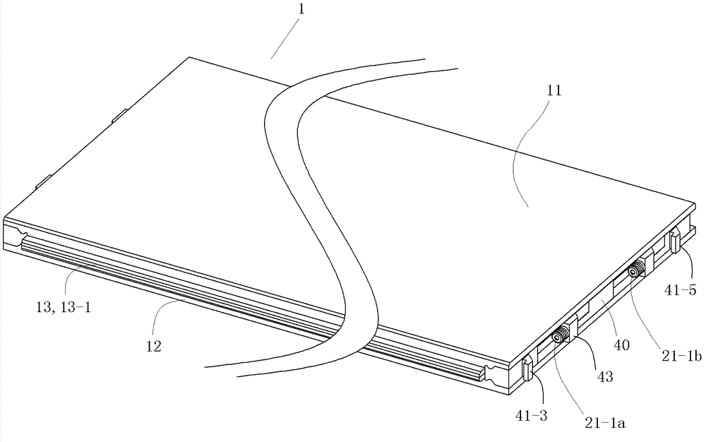
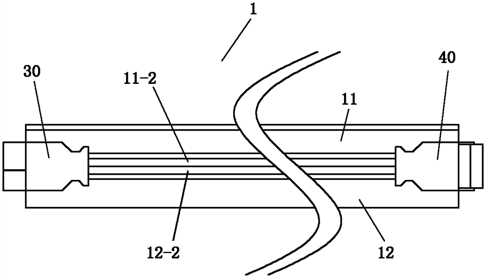
[0301] See Figure 9 , Figure 10 , Figure 17 , Figure 23 and Figure 30 , the electrothermal assembly 200 of this embodiment is a waterproof electric heating assembly, and the electrothermal assembly 200 can be used as a part of the self-heating floor or independently. The electrothermal component 200 includes a circuit device 20 , a first mounting base 30 and a second mounting base 40 . The first mounting seat 30 is a part that is plugged and electrically connected to each other by its socket part and the plug part of the second mounting seat 40 of the adjacent electrothermal component 200 when in use; the second mounting seat 40 is a part that is electrically connected by its plug The part is a component that is hermetically plugged and electrically connected to the socket part of the first mounting base 30 of the adjacent electrothermal component 200 .

[0302] See Figure 10 to Figure 12 , the circuit device 20 inclu...

Embodiment 2

[0384] (Example 2, electrothermal component)

[0385] The rest of this embodiment is the same as Embodiment 1, except that the cover plate 32 of the first mount 30 is not provided with the glue injection hole 32-2 and the exhaust hole 32-3, so the main body of the first mount 30 There is no need to inject insulating glue into the cavity.

[0386] The two cover plates 42 of the second mounting base 40 are not provided with the glue injection hole 42-2 and the exhaust hole 42-3, so the corresponding space formed by each cover plate 42 and the second seat body 41 does not need to inject insulation. glue.

Embodiment 3

[0387] (Example 3, electrothermal component)

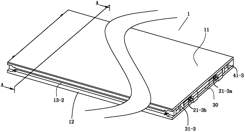
[0388] See Figure 31 and Figure 32 , the rest of this embodiment is the same as that of Embodiment 1, the difference is that: the insertion hole 30-2 in the front socket 30-3 of the first mounting seat 30 of the electrothermal component 200 and the insertion hole 30-2 in the rear socket 30-5 The insertion holes 30-4 in the socket are arranged in the same direction along the axis of the left and right direction; the two plugs 43 of the second mounting base 40 are also arranged in the same direction along the axis of the left and right direction.

[0389] The front buckle part 31-3 and the rear buckle part 31-5 of the first seat body 31 of the first mounting seat 30 are both the parts of the "L"-shaped hole in section, and the "L"-shaped One opening of the hole is to the left, and the other opening is upward; the front buckle part 41-3 and the rear buckle part 41-5 of the second seat body 41 of the second mounting seat 40 are c...


PUM


Abstract

Provided is a self-heating floor which comprises a floor main body and an electrothermal component, wherein the floor main body comprises an upper part main body and a bottom plate, the electrothermal component comprises a circuit device, a first mounting seat and a second mounting seat, the first mounting seat and second mounting seat of the electrothermal component are used as power supply plug connectors on the left and right sides of the floor main body, the circuit device of the electrothermal component and the corresponding parts of the first mounting seat and the second mounting seat are arranged between the upper part main body and the bottom plate; the first mounting seat is a component of which the socket part is hermetically plugged in and electrically connected with the plug part of the second mounting seat of the electrothermal component of the adjacent self-heating floor; and the second mounting seat is a component of which the plug part is hermetically plugged in and electrically connected with the socket part of the first mounting seat of the electrothermal component of the adjacent self-heating floor. The self-heating floor is simple in structure and convenient for realization of industrial production.

Description

technical field [0001] The invention relates to a product in the field of building decoration, in particular to a heating floor and heating components thereof. Background technique [0002] At present, the form of self-heating floor is electric heating floor. Electric heating floor has become a new heating method. It is to lay electric heating material in the floor and heat the floor by heating the electric heating material. [0003] Chinese patent document CN1034826C (application number 92114554.3) discloses an electric heating floor. The floor is provided with two through holes in the horizontal direction in the floor board, and the electric heating wire is inserted into the through hole. The holes are dislocated and the heating wire is worn off, and the port of the through hole adopts a bell mouth. In order to be more safe, the floor boards can be added with flame retardant materials, or the floor boards can be pressed with wood flour, asbestos powder and appropriate amo...

Claims


Application Information

Patent Timeline
Patent Type & Authority Patents(China)
IPC IPC(8): H05B3/22H05B3/04F24D13/02E04F15/02
CPCH05B3/26F24D2220/2081F24D13/024H05B3/18E04F15/02Y02B30/00
Inventor 葛林葛鑫琰
Owner 葛林
Why Eureka
Try Eureka