Automatic tracking seam welding/cutting manipulator

An automatic tracking and manipulator technology, applied in welding/cutting auxiliary equipment, welding equipment, welding equipment, etc., can solve the problems of high production equipment cost, fast tank speed, difficult eyes and hands, etc., to achieve easy maintenance and use, use The effect of long life and high degree of automation

Inactive Publication Date: 2012-06-27
柯友义
View PDF7 Cites 13 Cited by
  • Summary
  • Abstract
  • Description
  • Claims
  • Application Information

AI Technical Summary

Problems solved by technology

[0002] At present, there are roughly two welding methods for non-standard circular seams on circular metal tanks in the society: one is the general method: when welding the same model, first fix the welding torch frame to a position suitable for welding circular seams, The welder changes the torch head according to the trajectory of the seam. Disadvantages: the speed of the tank body is fast, the eyes and hands are difficult to synchronize, the welding effect is not ideal, there are many waste products, and there is a lot of air leakage (poor welding leads to leakage at the weld seam that can be repaired locally) Gas), labor and time-consuming, especially when welding thin materials, the welding workers have higher technical requirements; the other is laser positioning welding robot: it needs to scan while moving the welding torch head by computer control, the disadvantage is that the structure is complex, The cost of production equipment is high (each needs more than 200,000 yuan), the operation is difficult, and the maintenance is difficult

Method used


Image

  • Automatic tracking seam welding/cutting manipulator
  • Automatic tracking seam welding/cutting manipulator
  • Automatic tracking seam welding/cutting manipulator

Examples


Embodiment Construction

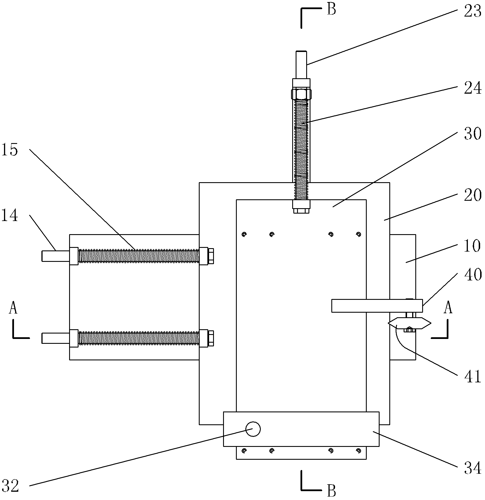
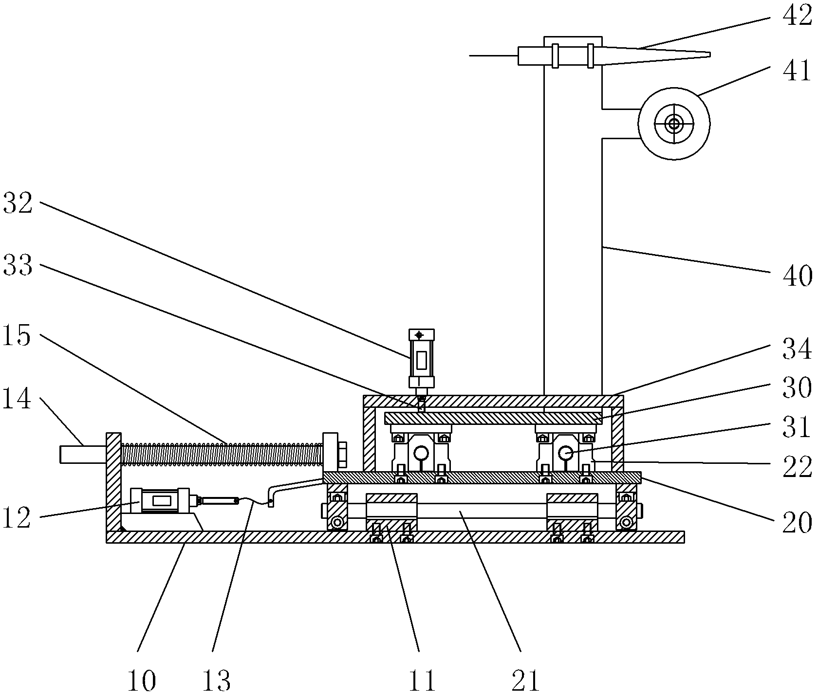
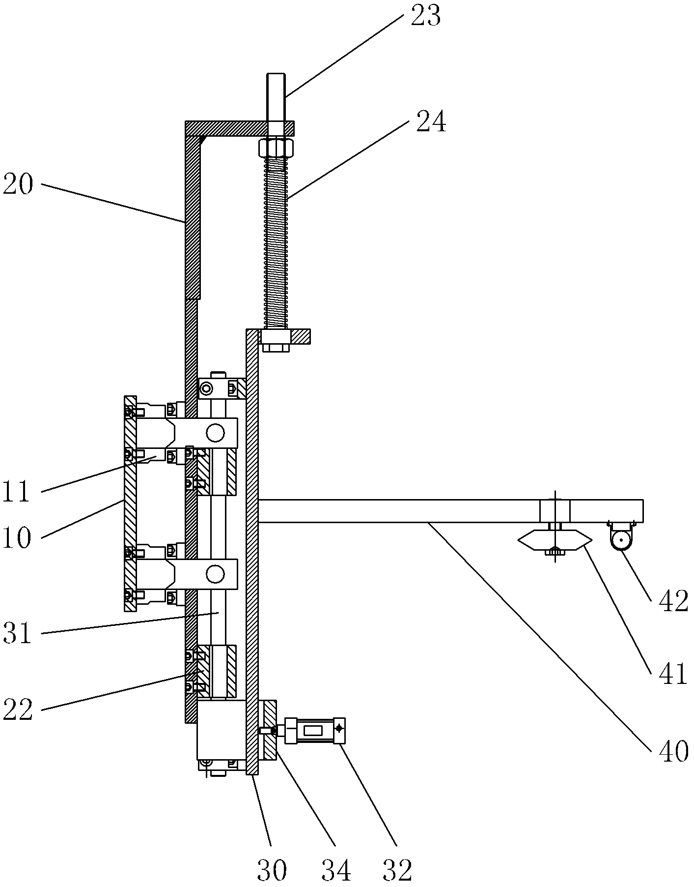
[0029] Below in conjunction with accompanying drawing, the present invention will be further described with specific embodiment, see Figure 1-6 :

[0030] The automatic tracking full seam seam welding / cutting manipulator is provided with a slide plate 20 moving laterally along the base on the base 10, and a compression spring 15 is provided between the slide plate 20 and the base 10 to push the slide plate 20 to move toward the workpiece 56 to be welded. The middle part of the tight spring 15 is provided with a guide shaft 14, and the slide plate 20 is provided with a slide table 30 that moves longitudinally along the slide plate 20, and between the slide plate 20 and the slide table 30 is provided with a compression spring 24 that promotes the slide table 30 to move longitudinally. The middle part of spring 24 is provided with guide shaft 23, and slide table 30 is provided with cantilever 40, and one side of cantilever 40 outer end is provided with the roller 41 that rolls a...


PUM


Abstract

The invention belongs to the technical field of a welding machine, and particularly relates to a creeping-type automatic tracking seam welding machine, which is characterized in that: a slide plate which can move transversely along a base is arranged on the base, a compression spring is arranged between the slide plate and the base, the slide plate is provided with a slide platform which moves longitudinally along the slide plate, a compression spring is arranged between the slide plate and the slide platform, the slide platform is provided with a cantilever, one side on the outer end part of the cantilever is provided with a roller which rolls along an annular seam of a work-piece to be welded, a welding torch is arranged on the cantilever at one side of the roller, a joint line of centers of the welding torch and of the roller is parallel to a central line in the length direction of the cantilever, and one side of the line of centers of the welding torch and the roller is provided with a press block or a press wheel for pressing one side welding element or an outer layer welding element. The automatic tracking seam welding / cutting manipulator has beneficial effects that: the automatic tracking seam welding / cutting manipulator has a simple structure and low production cost, is convenient to install, repair and use, can automatically track a seam trace to realize the movable welding, has high welding quality, and is suitable for seam welding annular weld seams.

Description

technical field [0001] The invention belongs to the technical field of welding auxiliary equipment, in particular to an automatic tracking full seam seam seam welding / cutting manipulator. Background technique [0002] At present, there are roughly two welding methods for non-standard circular seams on circular metal tanks in the society: one is the general method: when welding the same model, first fix the welding torch frame to a position suitable for welding circular seams, The welder changes the torch head according to the trajectory of the seam. Disadvantages: the speed of the tank body is fast, the eyes and hands are difficult to synchronize, the welding effect is not ideal, there are many waste products, and there is a lot of air leakage (poor welding leads to leakage at the weld seam that can be repaired locally) Gas), labor and time-consuming, especially when welding thin materials, the welding workers have higher technical requirements; the other is laser positionin...

Claims


Application Information

Patent Timeline
Patent Type & Authority Applications(China)
IPC IPC(8): B23K37/02B23K9/127
Inventor 柯友义
Owner 柯友义
Why Eureka
Try Eureka