
Critical method for manufacturing fiber array by semiconductor technology

An optical fiber array and semiconductor technology, applied in the field of optical fiber arrays, can solve the problems of difficult to eliminate angular divergence, large, generally up to 5.0 microns, and difficult optical fiber arrays.

Inactive Publication Date: 2012-06-27
SHENZHEN GIGALIGHT TECH
View PDF9 Cites 18 Cited by
  • Summary
  • Abstract
  • Description
  • Claims
  • Application Information

AI Technical Summary

Problems solved by technology

It is very difficult to manufacture fiber arrays with small spacing by using the drilling method, and the problem of angular divergence is difficult to eliminate, and the accuracy of the fiber array is low; the cumulative string length error of the close arrangement method is relatively large, generally up to 5.0 microns, and the accuracy of the fiber array is low; The V-shaped groove positioning method can only make multi-channel V-shaped grooves with a maximum accuracy of 1.0 microns, which still cannot meet the actual needs.

Method used


Image

  • Critical method for manufacturing fiber array by semiconductor technology
  • Critical method for manufacturing fiber array by semiconductor technology
  • Critical method for manufacturing fiber array by semiconductor technology

Examples


Embodiment Construction

[0031] In order to improve the precision of the fiber array, a key method of fabricating the fiber array using semiconductor technology with higher precision is proposed. The following will be described in conjunction with the accompanying drawings and specific embodiments.

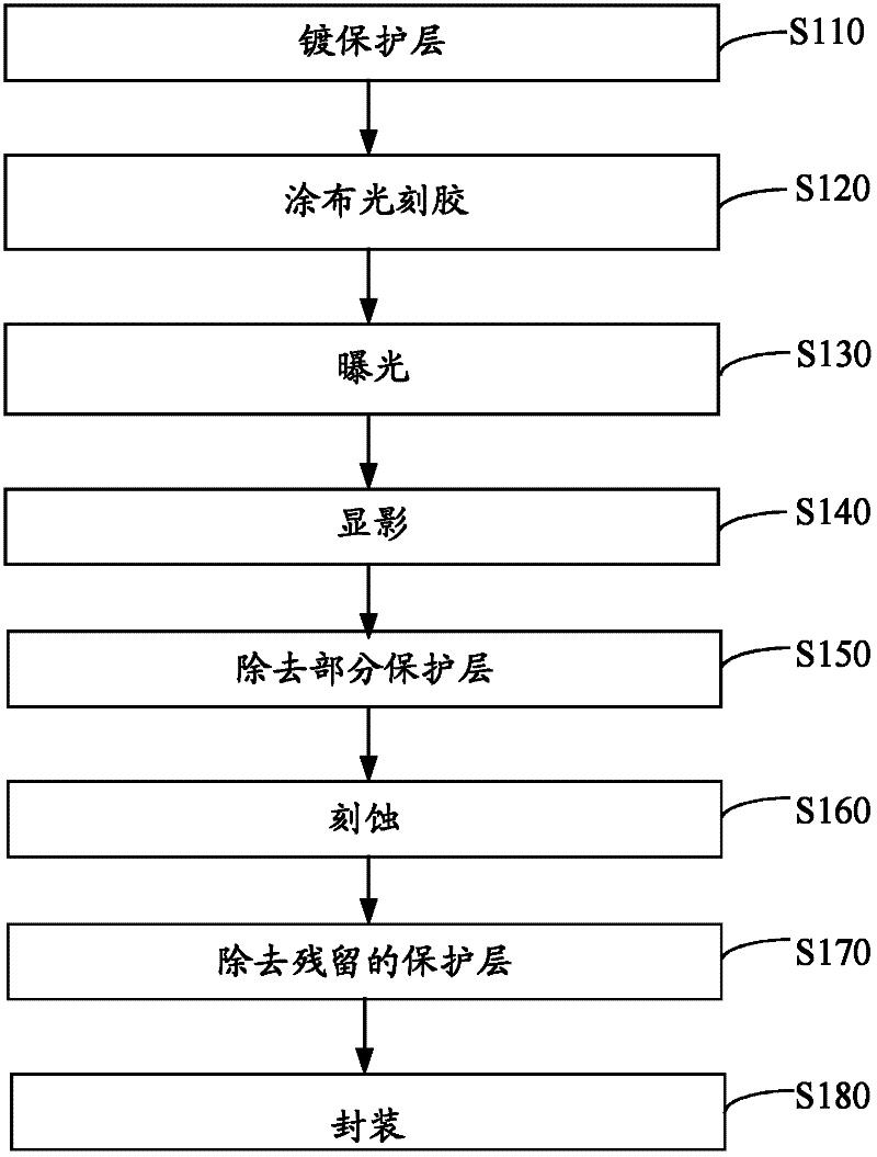
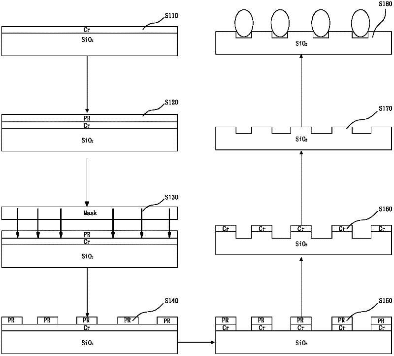
[0032] see figure 1 and figure 2 , a key method for fabricating an optical fiber array using a semiconductor process in one embodiment, comprising the following steps:

[0033] Step S110: plating a protective layer on the substrate.

[0034] The substrate can be a quartz glass substrate, a borosilicate glass substrate or a single crystal silicon substrate. Quartz glass substrates are produced by precision machining. From the perspective of reliability, it is better to use quartz glass substrates, and it is not easy to crack when grinding. In this embodiment, a quartz glass substrate is used.

[0035] First, the surface of the substrate is ground and polished to improve the adhesion of the protective...


PUM

PropertyMeasurementUnit
Depthaaaaaaaaaa

Abstract

The invention discloses a critical method for manufacturing a fiber array by a semiconductor technology. The method comprises the following steps of: plating a protective layer on a base plate; coating optical resist on the protective layer; exposing the optical resist; developing to remove a light-transmittable part in the optical resist; removing the part, which is not covered by the optical resist, in the protective layer; etching a U-shaped groove on the base plate by a dry etching technology; removing the protective layer remained on the base plate to get a fiber array location base plate; arranging fibers on the fiber array location base plate to form a fiber ribbon, and packaging the fiber ribbon to get the fiber array. By the dry etching technology, the high-precision U-shaped groove can be etched, and the fibers are located by the U-shaped groove, so that location precision of the fibers is improved, mean error of displacement is reduced greatly, and precision of the manufactured fiber array reaches 0.1 micrometer, thus, loss of optical signals is reduced, and the uniformity of the optical signals is improved.

Description

【Technical field】 [0001] The invention relates to the technical field of optical fiber arrays, in particular to a key method for manufacturing optical fiber arrays using semiconductor technology. 【Background technique】 [0002] With the recovery of the optical communication industry, the market for optical splitters is also booming. Plan Lightwave Circuit (PLC optical splitter) is a research hotspot at home and abroad today, and has a good application prospect. The PLC optical splitter is mainly used in the passive optical network of the access network to connect the central office with multiple users and realize fiber-to-the-home. The optical fiber array is the core component of the PLC optical splitter. The output end of the PLC optical splitter uses the optical fiber ribbon of the optical fiber array to couple with each output optical waveguide in the PLC. Therefore, the arrangement of the fiber ribbons of the fiber array directly affects the accuracy of the PLC optical...

Claims


Application Information

Patent Timeline
IPC IPC(8): G02B6/138G03F7/00
Inventor 王海东
Owner SHENZHEN GIGALIGHT TECH
Learn More