Device and method for laser micro shock dieless forming

A technology of moldless forming and laser shock, which is applied in the field of micro-electromechanical systems (Micr), can solve the problems of high transmission speed and placement accuracy, and the traditional method of blank clamping and positioning is no longer available, so as to achieve a wide range of applications and avoid Unfavorable structure and performance, high filming effect

Inactive Publication Date: 2012-07-04
SUZHOU UNIV OF SCI & TECH
View PDF7 Cites 14 Cited by
  • Summary
  • Abstract
  • Description
  • Claims
  • Application Information

AI Technical Summary

Problems solved by technology

Due to the light weight of the blank (typically only a few milligrams), the blank is greatly affected by the surface force, but the actual production has high requirements for the transmission speed and placement accuracy of the blank, which results in the traditional clamping and positioning of the blank. The method is no longer available; the test methods and test instruments for forming-related data such as strain rate, temperature field, etc. have also become very special at the micro scale, and traditional test theories, methods and equipment are no longer applicable

Method used


Image

  • Device and method for laser micro shock dieless forming
  • Device and method for laser micro shock dieless forming

Examples


Embodiment

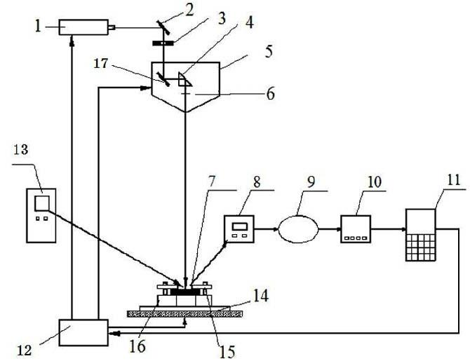
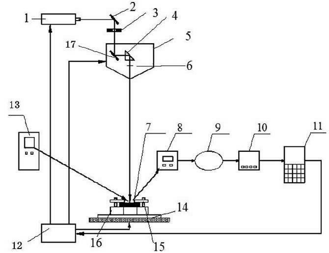
[0028] Such as figure 1 A laser micro-shock dieless forming device shown includes a laser 1, an optical path guiding system, a fixture system, a detection system and a control system; the optical path guiding system includes: a first reflector 2, a collimator 3 and The laser impact head 5; the laser impact head 5 is arranged in order from the light entering order, including: the second reflector 17, the triangular prism 4 and the focusing mirror 6; the tooling fixture system includes: a three-dimensional workbench 14, a fixture 15 , fixture base 16; the detection system includes: synchrotron radiation light source 13, detector 8, amplifier 9, pulse height analyzer 10, counter 11; the control system adopts industrial computer 12.

[0029] This embodiment also discloses a method of laser micro-impact moldless forming, the specific steps are as follows:

[0030] (A) Put the sample system in the tooling fixture system of the laser micro-impact moldless forming device, the samp...


PUM


Abstract

The invention discloses a device for laser micro shock dieless forming device. The device comprises a laser, a light path guiding system, a tooling fixture system, a detection system and a control system, wherein laser beams emitted by the laser are transmitted to the surfaces of workpieces, which are arranged in the tooling fixture system and are attached with flexible absorption layers through the light path guiding system; the absorption layers are induced by laser to generate high-temperature and high-voltage plasmas; the plasmas sharply expand and burst to generate strong shock waves to press towards surface layers of the workpieces and internal tissue structures, so that the workpieces are quickly and plastically deformed; the detection system is used for detecting shock regions on the workpieces and transmitting the detected data to the control system; the control system is used for receiving the data, analyzing and calculating the received data, comparing the analyzed and calculated result with the theoretical deformation of the point and acquiring energy required by next laser shock according to the comparison result; in addition, the control system is used for controlling the energy of the laser beams emitted by the laser next time and also controlling the tooling fixture system to do three-dimensional motion towards the next shock position. The device for the laser micro shock dieless forming, which is disclosed by the invention, is suitable for micro forming of materials which are difficult to form or cannot be formed by using a conventional method.

Description

technical field [0001] The present invention relates to the field of micro-electro-mechanical systems (Micro-Electro-Mechanical Systems, MEMS) manufacturing, in particular to a device and method for laser micro-shock dieless forming, which is suitable for micro-forming of metal thin films in MEMS, especially suitable for Microforming of materials that are difficult or impossible to microform by conventional methods. Background technique [0002] In the 1990s, microplastic forming, which applied traditional plastic processing technology to the manufacture of large-scale micro-metal components, appeared. The so-called micro-forming, micro-forming refers to the production of parts or structures at least in the sub-millimeter level in the two-dimensional direction by plastic processing [2]. With the development of large-scale integrated circuit manufacturing technology and the microelectronics industry represented by computers, more and more electronic components, electrical co...

Claims


Application Information

Patent Timeline
Patent Type & Authority Applications(China)
IPC IPC(8): B21D26/06
Inventor 汪帮富朱学莉宋娟李江澜祝勇俊
Owner SUZHOU UNIV OF SCI & TECH
Why Eureka
Try Eureka