Laser lap welding method

A lap welding and laser technology, applied in laser welding equipment, welding/welding/cutting items, welding equipment, etc., can solve the problems of reduction of welding length, burn-through, and reduction of laser beam energy density, etc. Effects of burden, improved quality, avoided space and cycle time

Inactive Publication Date: 2012-07-04
SUZUKI MOTOR CORP
View PDF7 Cites 13 Cited by
  • Summary
  • Abstract
  • Description
  • Claims
  • Application Information

AI Technical Summary

Problems solved by technology

However, as in JP2008-264793A figure 1 As shown, when the laser beam stops at the end of the weld and diverges, instead of improving holes and indentations can cause burn-through
In addition, although not clearly stated in JP2008-264793A, there still arises a problem that when the diverging operation is started just before the laser beam reaches the end of welding, the energy density of the laser beam decreases, so similar to the case using the above-mentioned method, the actual The welding length is reduced

Method used


Image

  • Laser lap welding method
  • Laser lap welding method
  • Laser lap welding method

Examples


no. 1 approach

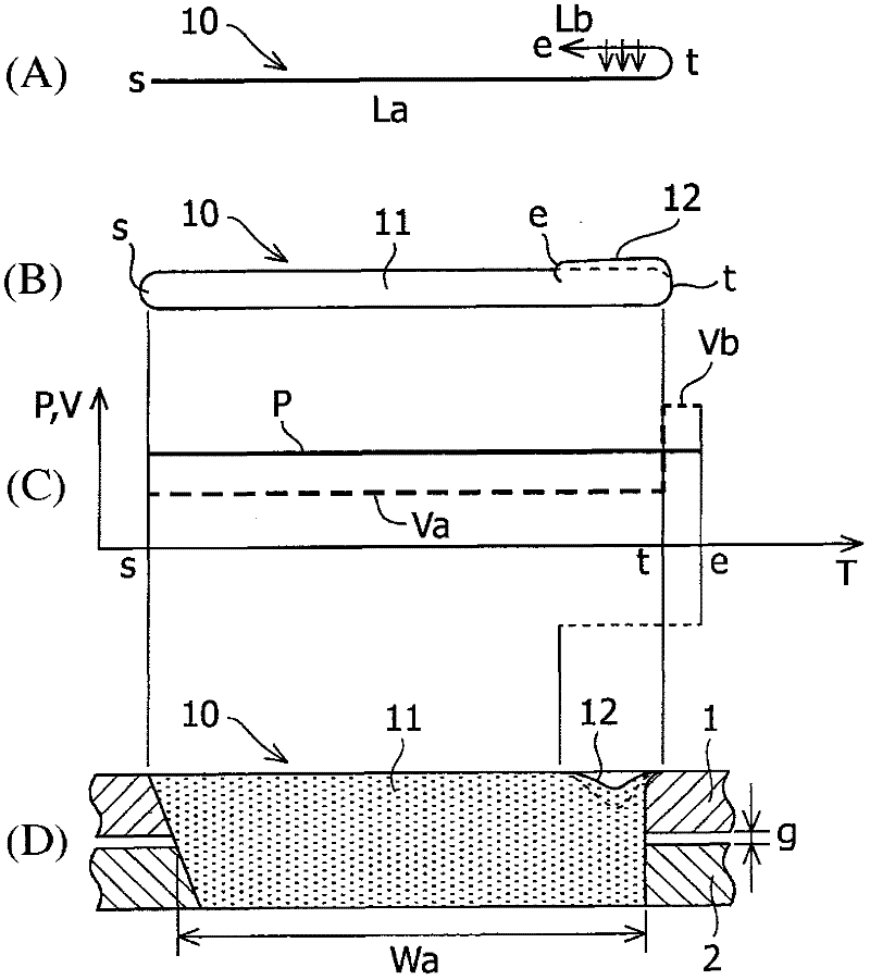
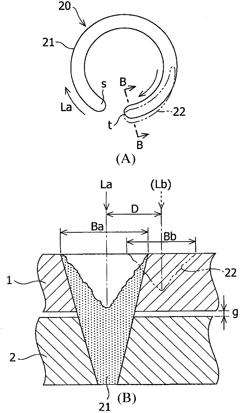
[0036] Similar to the first embodiment, laser scanning Lb in the backward direction is performed at high speed. Therefore, even when the laser output amount and spot diameter in the laser scanning Lb in the backward direction are the same as those in the laser scanning La in the forward direction, a reduction in the laser output amount (power density) is obtained. small effect. Therefore, the bead width Bb of laser scanning Lb in the backward direction is made narrower than the bead width Ba of laser scanning La in the forward direction while the depth of penetration is reduced to be smaller than the thickness of the upper steel plate 1 . When this state is reached, even by terminating the laser scanning Lb in the backward direction at the terminating end e, defects such as indentations are not left.

Embodiment

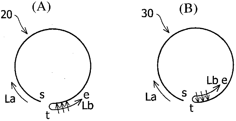
[0038] In order to check the effect of the laser lap welding method according to the present invention, experiments were carried out in the laser lap welding 20 and 30 according to the above-mentioned second embodiment and the third embodiment, while changing the laser scan La along the forward direction and along the The quality of the weld bead was evaluated in each case of the shift amount D between the laser scans Lb in the backward direction, and the scanning speed Vb of the laser scans Lb in the backward direction.

[0039] In the experiment, an optical fiber laser oscillator (with maximum output: 7 kW, diameter of transmission fiber: 0.2 mm) manufactured by IP G Photonics Corporation and a scanning head manufactured by HIGHYAG Laser Technology Corporation (processing focus diameter in focused state : 0.6mm). A non-plated steel sheet (1) with a thickness of 0.65 mm is superimposed on a plated steel sheet (2) with a thickness of 0.8 mm with gaps g=0.1 mm and g=0.2 mm as a...


PUM


Abstract

A laser lap welding method by irradiating of a laser beam from one side of a plurality of overlapped workpieces (1, 2), the method includes the steps of: scanning (La) the laser beam in the forward direction along a predetermined section of the workpieces; reversing the scanning direction of the laser beam at a terminating end (t) of the predetermined section; scanning (Lb) the laser beam in the backward direction and terminating of the irradiating of the laser beam onto the predetermined section, wherein the scanning of the laser beam in the backward direction is offset from the scanning of the laser beam in the forward direction such that a part of weld bead (12) formed by the laser scanning in the backward direction overlaps the weld bead (11) formed by the laser scan in the forward direction.

Description

technical field [0001] The present invention relates to a laser lap welding method, and more particularly to a laser lap welding method for improving holes, indentations, etc., generated at weld termination ends. Background technique [0002] In the laser lap welding method, a laser beam is irradiated onto the workpiece to heat and melt the material of the irradiated part with the light energy of the laser beam, and the laser lap welding method has the advantage that high-speed welding can be performed in a non-contact manner, but Has the problem of causing holes and indentations at the solder termination end. Therefore, this problem becomes a factor that limits the use of the laser lap welding method to only some automobile parts and prevents the laser lap welding method from being used in a car body welding process in which performance such as airtightness, water leakage, and Strict management of quality. [0003] The perforation and indentation caused at the laser weldi...

Claims


Application Information

Patent Timeline
Patent Type & Authority Applications(China)
IPC IPC(8): B23K26/20B23K26/00B23K26/21
CPCB23K26/0807B23K2201/34B23K2203/04B23K2201/006B23K26/246B23K2201/18B23K26/28B23K26/3206B23K26/3293B23K26/32B23K26/082B23K26/244B23K2101/006B23K2101/18B23K2101/34B23K2103/04B23K2103/08B23K2103/50B23K26/322
Inventor 林本和广藤沼雄大萩原宰薄井修一佐贯吉孝高桥昌裕
Owner SUZUKI MOTOR CORP
Why Eureka
Try Eureka