LED fluorescent lamp

A technology of LED fluorescent lamps and lamp holders, applied in the field of LED lamp tubes, can solve the problems of low luminous efficiency and good heat dissipation, and achieve the effects of good heat dissipation effect, low assembly cost and remarkable energy saving effect

Inactive Publication Date: 2012-07-04
WUXI AIR ELECTRONICS
View PDF13 Cites 6 Cited by
  • Summary
  • Abstract
  • Description
  • Claims
  • Application Information

AI Technical Summary

Problems solved by technology

[0004] For example, the domestic patent ZL200710123947.1 discloses a structure of an LED fluorescent tube. In this structure, the LEDs are only arranged at both ends of the tube, and an emission film and a diffusion film are arranged on the inner wall of the tube. This design cleverly avoids the The heat dissipation problem in the arrangement, but the LEDs arranged at both ends are lower in luminous efficiency than multiple arrays in the lamp tube, and it is impossible to really achieve good heat dissipation and uniform light and shade.

Method used


Image

  • LED fluorescent lamp
  • LED fluorescent lamp
  • LED fluorescent lamp

Examples


Embodiment 1

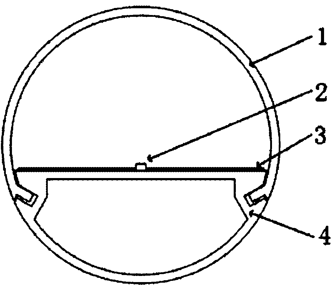
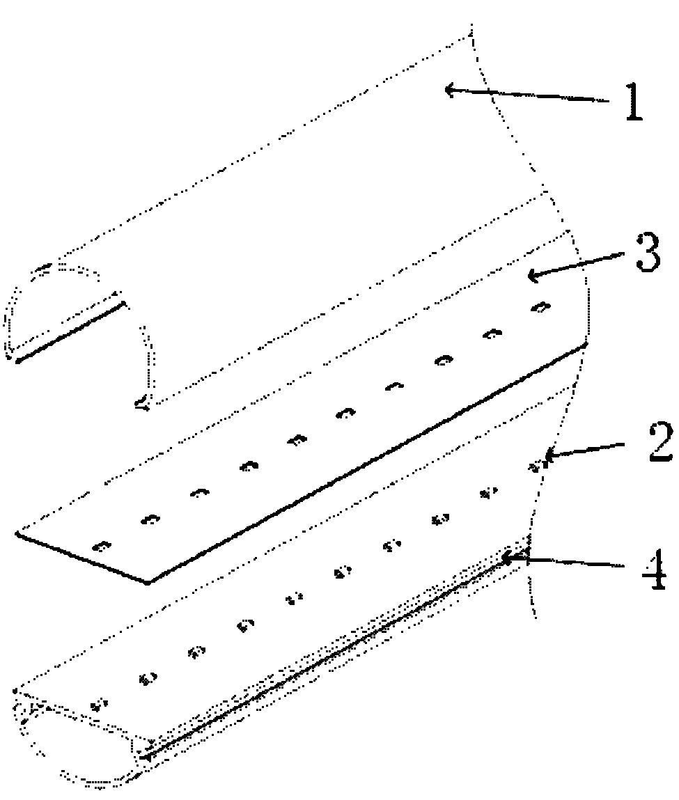
[0030] Such as figure 1 , figure 2 As shown, the LED fluorescent lamp includes a PC lampshade, LED, reflective film, printed circuit board and lamp holder as an integrated structure. There are several LEDs on the printed circuit board. The LEDs use medium and high-power LEDs. The quantity is less than 100 pieces. The LED light-emitting surface is covered with a high-reflection film except for the LED light-emitting point. The high-reflection film can be made of, for example, E6QV material, or it can be sprayed or printed with a high-reflection material. The integrated structure of the printed circuit board and the lamp holder is formed by bonding the insulating layer and the circuit layer to the lamp holder with pressure-sensitive adhesive or directly. The insulating layer is composed of epoxy film, glass fiber cloth or polyimide, and the circuit layer is etched copper foil. A built-in power supply is arranged in the lamp holder, and the built-in power supply adopts a high...

Embodiment 2

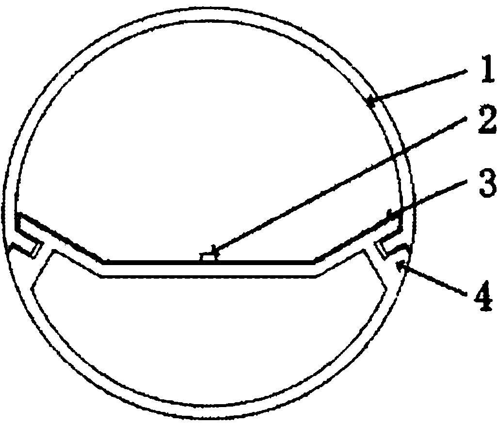
[0032] Such as image 3 , Figure 4 As shown, the difference from Embodiment 1 is that the integrated structure of the printed circuit board and the lamp holder can be a sunken trapezoidal structure.

Embodiment 3

[0034] Such as Figure 5 , Figure 6 As shown, the difference from Example 1 is that a groove is provided on the top surface of the lamp holder, and a printed circuit board is arranged in the groove, and the top surface of the lamp holder is covered with a high-reflection film, and a high-reflection material can also be sprayed or printed on the surface .


PUM


Abstract

The invention relates to the technical field of LED lamp tubes, in particular to an LED fluorescent lamp. The LED fluorescent lamp comprises a lamp shade, LEDs, reflecting films, a printed circuit board and a lamp holder, wherein a plurality of LEDs are arranged on the printed circuit board. The LED fluorescent lamp is characterized in that high reflecting films are fully distributed on the light-emitting surfaces except LED light-emitting points of the LEDs, or high reflecting materials are sprayed and printed on the surfaces of the LEDs. An insulating layer and a circuit layer in an aluminum substrate are directly attached to the aluminum heat radiating lamp holder to enable the printed circuit board and the lamp holder to from an integrated structure. According to the LED fluorescent lamp, the problems that the light transmittance of a PC (Poly Carbonate) lamp shade of the LED lamp tube is low and the LED lamp tube is non-uniform in brightness and is poor in heat radiation are better solved.

Description

[technical field] [0001] The invention relates to the technical field of LED lamp tubes, in particular to an LED fluorescent lamp. [Background technique] [0002] Conventional LED tubes, in order not to see light spots and evenly emit light, use high-atomized PC lampshades, densely covered with low-power LEDs, and 1.2-meter tubes. Most of the lamp beads are more than 200, and the light output transmittance is low. It is about 85% (the transmittance is the output luminous flux of the lamp after adding the PC lampshade divided by the output luminous flux of the lamp without the PC lampshade). The result of this is that the cost of making LED fluorescent lamps is high, and the reliability is low, and compared with medium and high power LEDs, low-power LEDs have lower heat resistance and lifespan. After technical analysis and experimental verification, it is found that the transmittance of the same material on the spherical PC lampshade can reach 95%, while the transmittance of...

Claims


Application Information

Patent Timeline
Patent Type & Authority Applications(China)
IPC IPC(8): F21S2/00F21V7/22F21V29/00F21V19/00F21Y101/02F21K9/20F21V29/507F21Y115/10
Inventor 顾毅天
Owner WUXI AIR ELECTRONICS
Why Eureka
Try Eureka