
Optical detection system using additional light sources

A detection system and positioning detection technology, applied in the direction of optical devices, measuring devices, instruments, etc., can solve the problems of inability to track the historical process of error changes, many manual detection procedures, and error-prone, so as to achieve a perfect clinical treatment quality management system, Effect of filtering out subjective interference factors and improving frequency and efficiency

Inactive Publication Date: 2012-07-04
杨诚
View PDF5 Cites 3 Cited by
  • Summary
  • Abstract
  • Description
  • Claims
  • Application Information

AI Technical Summary

Problems solved by technology

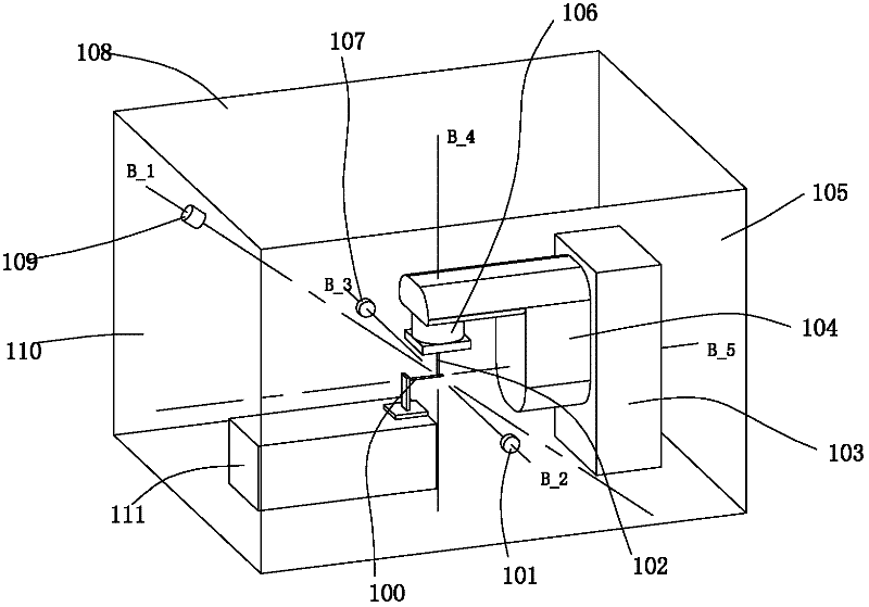
[0013] 2. Using the detection method of multiple positioning and indirect measurement, it is easy to superimpose new errors
Such as the installation position error of the probe rod 102, the length and deflection error of the probe rod 102, the deflection error of the small machine head 106, etc., they will all affect the calibration offset of the final isocenter point
[0014] 3. There are many manual inspection procedures, long time-consuming, error-prone, high experience requirements for operators, and cannot meet the strict daily inspection frequency
[0015] 4. It can only be qualitative, not quantitative, cannot digitally display the detected errors, cannot track the historical process of error changes, and everyone has a different understanding of the error phenomenon, which is easy to introduce subjective factor deviation
[0016] Using the above method, the process for doctors to verify the positioning accuracy of related equipment will become very cumbersome and tiring

Method used


Image

  • Optical detection system using additional light sources
  • Optical detection system using additional light sources
  • Optical detection system using additional light sources

Examples


Embodiment Construction

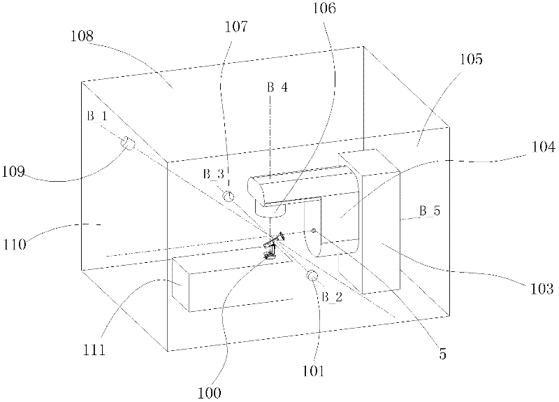
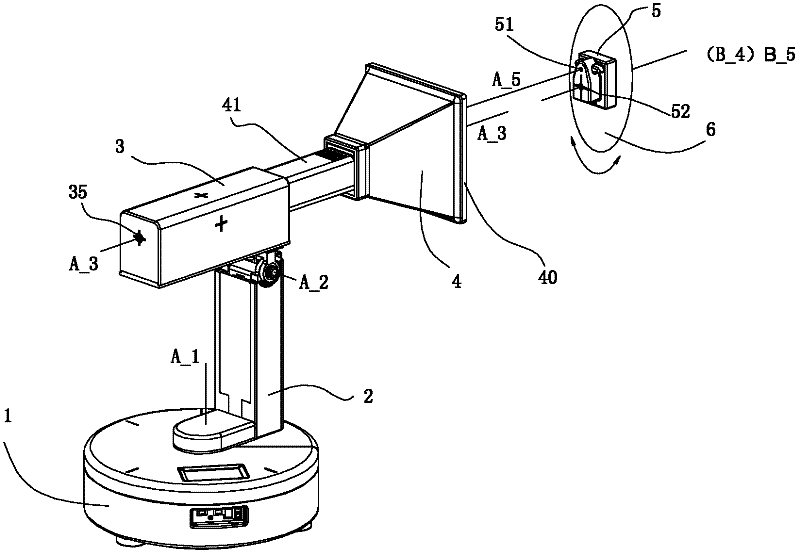
[0046] An optical detection system for the isocenter point of medical radiation-related equipment, such as Figure 3 to Figure 8 As shown, it includes a detection host and a controllable micro-laser generator 5, wherein the controllable micro-laser generator 5 is an additional light source, which can cooperate with the detection host to optically detect the isocenter of the device that does not emit light itself.

[0047] like image 3 , Figure 4 , Figure 5 As shown, the detection host includes a base 1 , a vertical slide rail 2 , a rotating slide rail 3 and a vision probe 4 . The base 1 is provided with a communication interface 11 to connect with an external PC. The vertical slide rail 2 can rotate 360° angle a1 around the central axis A-1 axis of the host base 1; the rotating slide rail 3 can rotate around the rotation axis A-2 on the vertical slide rail 2 (perpendicular to Figure 5 The paper surface in the paper) rotation angle a2 (a2 is 0 degree to 95 degrees); the...


PUM


Abstract

The invention discloses an optical detection system using additional light sources, which is used for detection of isocenter points of radiation equipment and radiotherapy equipment and comprises a detection main unit and a controllable miniaturized laser generator. The controllable miniaturized laser generator comprises a laser light and an emission window for the laser light. The positioning detection main unit comprises a base and a visual probe mounted on the same, a flare induction screen is mounted on the visual probe and capable of moving on the base, and light emitted by the controllable miniaturized laser generator reaches the flare induction screen. The controllable miniaturized laser generator is used as an additional light source used with the detection main unit for detectionof the isocenter points of radiation equipment and radiotherapy equipment, operation is easy, detection is greatly facilitated, a spatial line equation of light beams can be established to obtain theisocenter points of the equipment without using mobile detection systems, detection precision is high, the system is light in equipment weight and small in size, and the detection time is short. The optical detection system is applicable to detection of physical isocenter points of medical radiotherapy equipment.

Description

[0001] This case is a divisional application of the following invention patent: Application number: 201010546220.6 Application date: November 16, 2010 Invention name: A method and device for detecting the central point of radiation and radiotherapy equipment technical field [0002] The invention relates to an optical detection system which utilizes an additional light source to detect the isocenter of light radiation-related equipment, especially medical radiation and radiotherapy equipment. Background technique [0003] Many large-scale equipment need to use beams to simulate their own positioning coordinate system in space, and determine the spatial position of the origin of coordinates by crossing beams, so as to ensure the accuracy and precision of other related supporting equipment in spatial positioning and relative movement. Especially, in the field of medical radiation inspection and radiation therapy, radiation inspection equipment (such as: CT, x-ray simulation pos...

Claims


Application Information

Patent Timeline
Patent Type & Authority Applications(China)
IPC IPC(8): G01B11/00
Inventor 杨诚
Owner 杨诚
Learn More