Light source device, light source generation method and laser projector comprising light source device

A light source device and light source technology, applied in the field of laser projection, can solve problems such as low energy utilization, energy loss, and difficult assembly, and achieve the effects of improving energy utilization, reducing energy loss, and compact structure

Active Publication Date: 2012-07-04
HISENSE
View PDF3 Cites 25 Cited by
  • Summary
  • Abstract
  • Description
  • Claims
  • Application Information

AI Technical Summary

Problems solved by technology

[0012] Although the above-mentioned existing light source device enables laser projection to be realized, from figure 1 It can be found very intuitively that there are too many optical components and the optical path is too long in the light source device.
Every time the beam passes through an optical component, it will lose some energy, and the length of the optical path will also affect the energy loss of the beam
Therefore, each light source is figure 1 After transmission in the light source device shown, the energy will be greatly reduced, and the energy utilization rate is low
[0013] Moreover, in the existing light source device, the number of optical components is large, resulting in a relatively complex overall structure, and the volume will be correspondingly large
Such a light source device obviously cannot meet the increasingly obvious miniaturization requirements
[0014] In addition, in order to ensure the normal operation of the light source device, it is necessary to ensure the correctness of the installation position and relative position of each optical component, which is difficult to assemble; when an optical component fails, the problem cannot be found in a short time, and the maintenance is difficult high

Method used


Image

  • Light source device, light source generation method and laser projector comprising light source device
  • Light source device, light source generation method and laser projector comprising light source device
  • Light source device, light source generation method and laser projector comprising light source device

Examples


no. 1 example

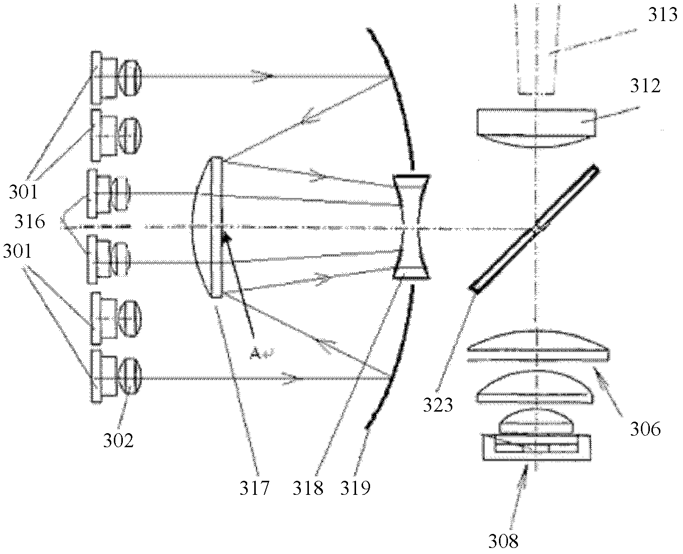
[0058] image 3 is a schematic structural view of the light source device according to the first embodiment of the present invention.

[0059] see image 3 , in this embodiment, the light sources include a first light source 301 , a second light source 308 and a third light source 316 each having a different wavelength. In addition to the light source, the light source device includes: a collimator lens system 302 , a first condenser lens 317 , a negative focal length lens 318 , a reflection mirror 319 , a second condenser lens 312 and a light rod 313 . The first condenser lens 317, the negative focal length lens 318, the reflector 319 and the first dichroic film 323 are all installed concentrically, and the optical axes of the second condenser lens 312 and the light rod 313 are perpendicular to the optical axes of the concentrically installed components. Hereinafter, the direction connecting the centers of the components installed concentrically is referred to as the first ...

no. 2 example

[0076] Figure 4 is a schematic structural view of a light source device according to a second embodiment of the present invention.

[0077] see Figure 4 , this embodiment introduces the fluorescent wheel 422 on the basis of the first embodiment, so that the first light source 401 is used as the excitation light, and when the area of ​​the fluorescent wheel is irradiated with phosphor powder, a second light source (not shown) is generated. ). The fluorescent wheel 422 rotates under the drive of the driving motor 411 so as to alternately receive the first light source 401 in the phosphor area or the transmission area.

[0078] In order for the light-receiving device to obtain the light beam of the dominant wavelength corresponding to the first light source 401, in addition to the first light source 401 whose center is emitted in the first direction as the excitation light of the second light source, an additional The first light source 425 emitting in two directions has the...

no. 3 example

[0096] Figure 5 is a schematic structural view of a light source device according to a third embodiment of the present invention.

[0097] see Figure 5 , the type of light source and the optical path of each light source in this embodiment are exactly the same as those in the second embodiment, except that the light receiving device here is a fly-eye lens 524, so that the light source device of this embodiment can be used in a fly-eye projector.

[0098] The light sources in this embodiment are the first light source 501 for exciting the second light source, the third light source 516 and the first light source 525 having the same dominant wavelength as the first light source. The light source device includes: a collimating lens system 502, a first condenser lens 517, a negative focal length lens 518, a reflector 519, a second dichroic film 505, a third dichroic film 520 and a fourth dichroic film 521 X mirror, fluorescent wheel 522, driving motor 511, fifth condenser lens...


PUM


Abstract

The invention discloses a light source device, a light source generation method and a laser projector comprising the light source device. The light source device comprises light sources comprising a first light source, a second light source and a third light source which are provided with different main wavelengths; the light source device further comprises collimation part, a reflection part, a convergency and refection part, a convergency part and a dichroic part, wherein the collimation part is positioned on emergent sides of the first and the third light sources and is used for aligning the received light sources; the reflection part is used for reflecting the aligned first light source to the convergency and refection part; the convergency and refection part is used for reflecting the first light source reflected by the reflection part and converging the aligned third source; the convergency part is used for converging the first and the third light sources; and the dichroic part is used for leading the second light source plus the first and the third light source from the convergency part to be incident into a light receiving part in the same direction. By adopting the light source device, the number of parts in the light source device can be effectively reduced, a light path is simplified, the energy utilization rate is increased, and the mounting and the maintenance are simple.

Description

technical field [0001] The invention relates to laser projection technology, in particular to a light source device, a method for generating a light source and a laser projector including the light source device. Background technique [0002] In recent years, laser projectors have been widely used in various occasions due to their simple principle, low manufacturing difficulty, rich colors, and small visual impact, such as TV projection, miniature projection, and some commercial and entertainment systems. [0003] As we all know, an optical picture needs to be composed of at least light waves of different dominant wavelengths, such as blue, green and red light waves. Based on the current technology, usually a light source of one wavelength is used as excitation light to generate a light source of another wavelength, and then time-shared emission with light sources of other wavelengths to display various images on the projection screen. For example, the blue laser emitted by...

Claims


Application Information

Patent Timeline
Patent Type & Authority Applications(China)
IPC IPC(8): G03B21/20G02B27/30G02B27/28G02B27/00F21V13/00
Inventor 李巍田有良闫国枫陈昱刘风雷
Owner HISENSE
Why Eureka
Try Eureka