Liquid-cooled radiating device

A liquid-cooled heat dissipation and liquid-cooled head technology, which is applied in cooling/ventilation/heating transformation, instruments, electrical digital data processing, etc., can solve problems that do not meet energy conservation and environmental protection, and achieve design cost saving, cost reduction, and small size Effect

Inactive Publication Date: 2012-07-04
中山市云创知识产权服务有限公司
View PDF6 Cites 21 Cited by
  • Summary
  • Abstract
  • Description
  • Claims
  • Application Information

AI Technical Summary

Problems solved by technology

However, for a container data center, a large amount of heat will be generated due to a large number of calculations. When using air cooling to dissipate heat, a large number of radiators and fans are required to dissipate the heat i

Method used


Image

  • Liquid-cooled radiating device
  • Liquid-cooled radiating device
  • Liquid-cooled radiating device

Examples


Embodiment Construction

[0033] The present invention will be further described below in conjunction with the embodiments with reference to the accompanying drawings.

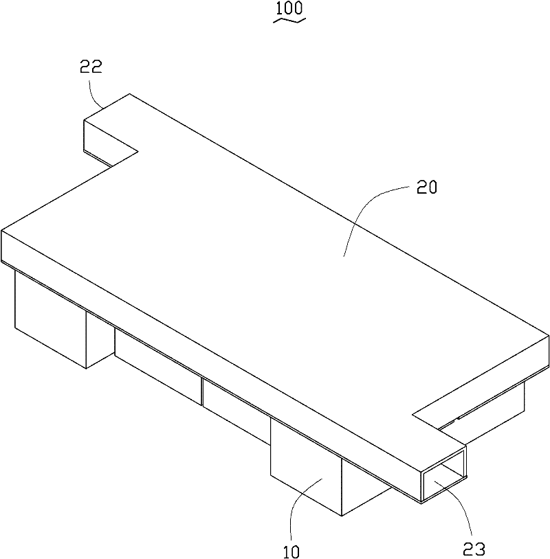
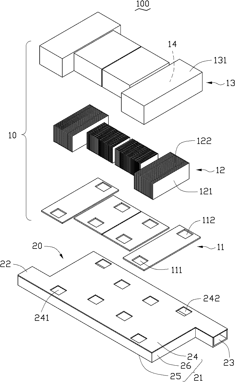
[0034] figure 1 and figure 2 Shown is a liquid cooling heat sink 100 according to an embodiment of the present invention. The liquid cooling device 100 is used to dissipate heat for an electronic device, such as a plurality of heat-generating electronic components in a containerized data center. The liquid cooling device 100 includes a box body 20 and a plurality of liquid cooling heads 10 combined at the bottom of the box body 20 . The plurality of liquid cooling heads 10 are used to respectively contact with a plurality of heat-generating electronic components (not shown in the figure) so as to respectively absorb the heat generated by the plurality of heat-generating electronic components. In this embodiment, the cooling medium is water. Understandably, the cooling medium can also be other liquids.

[0035] Each liquid cooling...


PUM


Abstract

A liquid-cooled radiating device is used for radiation of at least one heating electronic component, and comprises at least one liquid-cooled head and a container connected with the liquid-cooled heads. A closed containing space is formed in each liquid-cooled head which is provided with a first liquid inlet and a first liquid outlet, the container comprises a liquid inlet passage and a liquid outlet passage which are isolated from each other, a liquid inlet pipe for cooling media to inflow is arranged on the side of the container as same as that of the liquid inlet passage and is communicated with the first liquid inlets, and a liquid outlet pipe for cooling media to flow out is arranged on the side of the container as same as that of the liquid outlet passage and is communicated with the first liquid outlets. The liquid-cooled radiating device is small in size, simpler than an air-cooled radiating device in structure, low in development cost and capable of relieving cost burden for redesign and redevelopment under different platforms and effectively saving design cost.

Description

technical field [0001] The invention relates to a liquid cooling and heat dissipation device, in particular to a liquid cooling and heat dissipation device for heat dissipation of heating electronic components. Background technique [0002] In electronic devices such as rack servers, storage and workstations, the space, power consumption and cost of the thermal architecture are key considerations. The heat dissipation structure of traditional electronic devices is mostly air-cooled, which generally includes a heat sink attached to the heat-generating electronic component and a fan combined with the heat-sink to dissipate heat from the heat-generating electronic component. However, for a container data center, a large amount of calculation will generate a lot of heat. When using air cooling for heat dissipation, a large number of radiators and fans are required to dissipate the heat in a timely manner. However, the increase in the number of fans means that the total energy c...

Claims


Application Information

Patent Timeline
IPC IPC(8): H01L23/473H05K7/20G06F1/20
Inventor 谭子佳
Owner 中山市云创知识产权服务有限公司
Why Eureka
Try Eureka