
Distributed power flow controller based on line cubic harmonic wave

A power flow controller, sub-harmonic technology, applied in harmonic reduction devices, AC networks to reduce harmonics/ripples, flexible AC transmission systems, etc., can solve the paralysis of transmission lines, high investment costs, and is not widely used and other problems, to achieve the effect of reducing insulation cost, improving reliability, and facilitating popularization and application.

Inactive Publication Date: 2012-07-04
WUHAN UNIV OF TECH
View PDF3 Cites 12 Cited by
  • Summary
  • Abstract
  • Description
  • Claims
  • Application Information

AI Technical Summary

Problems solved by technology

However, such a powerful UPFC has not been widely used in power systems, the main reasons are as follows: 1. UPFC is formed by two identical converters (VSC, voltage source converter) back to back through DC capacitive coupling. Faults will be transmitted to the entire transmission line through the DC capacitor, causing the entire transmission line to be paralyzed; 2. UPFC often uses high-power three-phase converters, coupled with high-voltage insulation between phases, making the investment cost high

Method used


Image

  • Distributed power flow controller based on line cubic harmonic wave
  • Distributed power flow controller based on line cubic harmonic wave
  • Distributed power flow controller based on line cubic harmonic wave

Examples


Embodiment Construction

[0022] Embodiments of the present invention will be further described below in conjunction with the accompanying drawings.

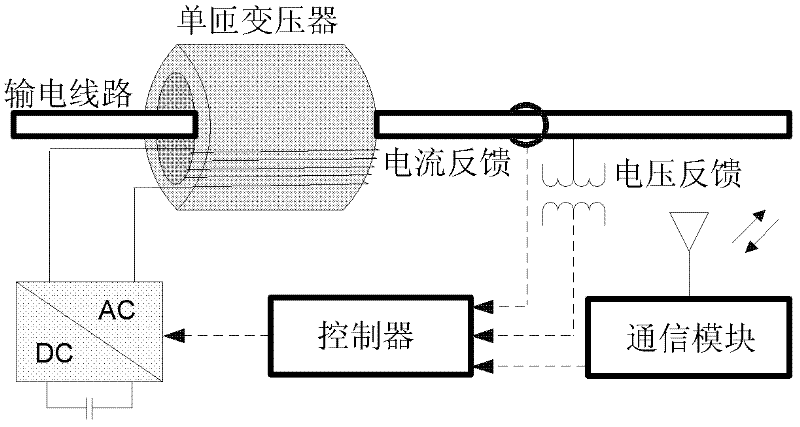
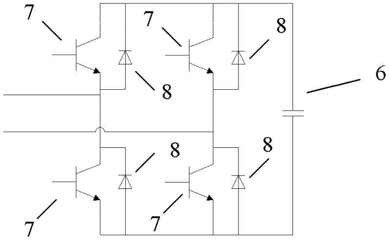
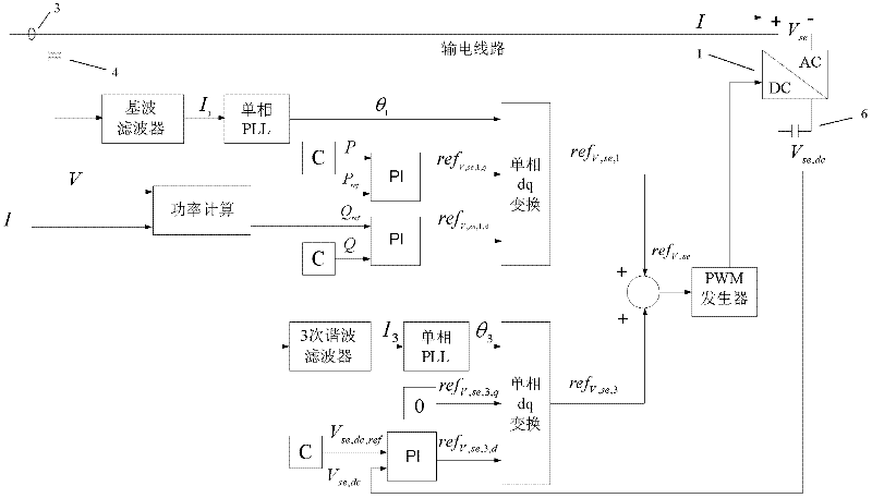
[0023] see figure 1 , figure 2 , image 3 and Figure 4 , a distributed power flow controller based on the third harmonic of the line, including a transmission line 5 with a power flow controller unit 9, and a first Y-Δ transformer 10 and a second Y-Δ transformer 10 at both ends of the transmission line 5 Y-Δ type transformer 12, the neutral point of the Y-shaped winding of the first Y-Δ type transformer 10 is connected with the 3rd harmonic power supply 11, and the neutral point of the Y-shaped winding of the second Y-Δ type transformer 12 is grounded; The power flow controller unit 9 described above includes a converter 1, the positive pole of the DC side of the converter 1 is connected to one end of the DC capacitor 6, the negative pole of the DC side of the converter 1 is connected to the other end of the DC capacitor 6, and the converter 1 passe...


PUM


Abstract

The invention relates to a distributed power flow controller based on line cubic harmonic waves, comprising a power transmission line, wherein a first Y-delta type transformer and a second Y-delta type transformer are installed on two ends of the power transmission line; a power flow controller unit is installed on the power transmission line; the distributed power flow controller also comprises a cubic harmonic power supply, wherein the cubic harmonic power supply is connected with a neutral point of the Y-type winding of the first Y-delta type transformer; the neutral point of the Y-type winding of the second Y-delta type transformer is grounded; the power flow controller unit comprises a converter, wherein a positive pole of the converter direct-current side is connected with one end of a capacitor; the negative pole of the converter direct-current side is connected with the other end of the capacitor; the converter is connected with the power transmission line in series by a single-turn coupling transformer; the converter is connected with an output end of the controller; an input end of the controller is connected with a current mutual inductor and a voltage mutual inductor on the power transmission line. The invention can improve reliability of the power transmission line.

Description

technical field [0001] The invention relates to the technical field of flexible alternating current transmission, in particular to a distributed power flow controller based on the third harmonic of the line. Background technique [0002] With the development of distributed generation (DG, distributed generation) technology, more and more small and medium-sized DGs are connected to the distribution network side of the power system. The power flow of the transmission is reversed. Due to the climate variability of the renewable energy DG, the entire power transmission system needs power control to compensate for the intermittent nature of the DG; the continuous growth of user loads requires power flow control methods to improve the power transmission capacity of existing lines. To slow down or reduce the need for high-cost new lines; the power blocking between tie lines, the existence of circulating power that causes huge line loss, and the bidirectional flow between tie lines ...

Claims


Application Information

Patent Timeline
Patent Type & Authority Applications(China)
IPC IPC(8): H02J3/01H02J3/18
CPCY02E40/18Y02E40/10Y02E40/40
Inventor 唐爱红卢俊黄萍许湘莲陈跃鹏
Owner WUHAN UNIV OF TECH
Learn More