Expandable mounting head for chip mounter

A technology of placement head and placement machine, which is applied in the direction of assembling printed circuits with electrical components, can solve the problems of complex assembly, increased installation difficulty, and high cost, and achieves convenient structural installation, fast placement speed, and high placement accuracy. Effect

Inactive Publication Date: 2012-07-04
CHANGAN UNIV
View PDF6 Cites 9 Cited by
  • Summary
  • Abstract
  • Description
  • Claims
  • Application Information

AI Technical Summary

Problems solved by technology

[0003] At present, the commonly used mounting head generally adopts the following methods for vertical feed: 1) The transmission mode of the gear / rack structure, which is relatively traditional, and the implementation of the actuator is simple, but this method has a great impact on the movement of the mounting spindle. It is difficult to improve the control accuracy; 2) Synchronous conveyor belt plus stepping motor drive structure, the control accuracy of this method is acceptable, but the structure is easily damaged and will increase the overall size; 3) Servo motor form, but the assembly of this form is complicated and precise Not high, at the same time the cost is high
[0004] The following types of structures are often used by the placement head to adjust the angle of the patch components: 1) Two stepping motors plus a synchronous belt form. The angle of the component is adjusted, but the overall volume of the structure is large, and the inertia increases due to the increase in weight, which will inevitably affect the mounting accuracy; Coaxial, which increases the difficulty of installation and also reduces the placement accuracy

Method used


Image

  • Expandable mounting head for chip mounter
  • Expandable mounting head for chip mounter
  • Expandable mounting head for chip mounter

Examples


Embodiment Construction

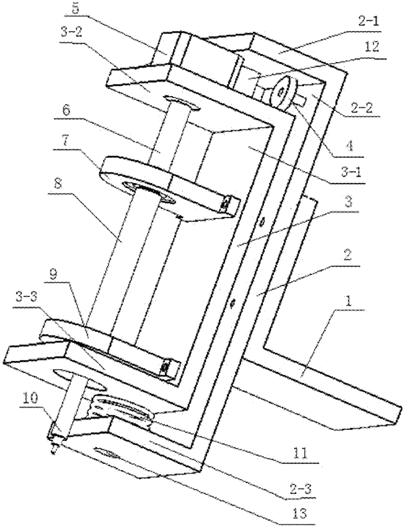
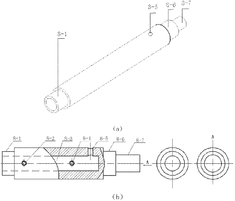
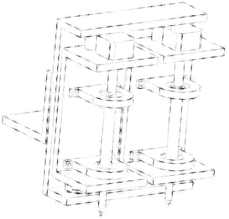
[0027] See Figure 1 ~ Figure 3 , The expandable placement head of the present invention includes a support base 2, a guide rail base 3, a cam 4, a reduction stepper motor 5, a coupling 6, and a hollow tube 8.

[0028] Among them, the supporting seat 2 is a "U"-shaped frame composed of the supporting seat rear plate 2-1 and the supporting seat top plate 2-2 and the supporting seat bottom plate 2-3 at both ends; the guide rail seat 3 is composed of the guide rail seat rear plate 3- 1 and the "U"-shaped frame composed of the rail seat top plate 3-2 and the rail seat bottom plate 3-3 at both ends; the length of the rail seat rear plate 3-1 is smaller than the length of the support seat rear plate 2-1.

[0029] The support seat top plate 2-2 and the support seat bottom plate 2-3 are both provided with a through hole 13 in the center position. The rail seat top plate 3-2 is equipped with a rail shaft 12 perpendicular to the guide rail seat top plate 3-2, and the guide rail seat bottom p...


PUM


Abstract

The invention discloses an expandable mounting head for a chip mounter. The expandable mounting head comprises a supporting seat, a guide rail seat, a cam, a speed-reducing stepping motor, a coupler and a hollow pipe, wherein the supporting seat is a U-shaped frame formed by a supporting seat rear board, supporting seat top plate and a supporting seat bottom plate, wherein the supporting seat top plate and the supporting seat bottom plate are arranged at the two ends of the supporting seat rear board; the guide rail seat is the U-shaped frame formed by a guide rail rear board, guide rail top plate and a guide rail bottom plate, wherein the guide rail top plate and the guide rail bottom plate are arranged at the two ends of the guide rail rear board; and the guide rail rear board is shorter than the supporting seat rear board. The expandable mounting head for the chip mounter is the key constituent part of an economical and simple chip mounter, adopts the cam and a spring to realize a feeding mode of the mounting head in the vertical direction, adopts one speed-reducing stepping motor and the hollow pipe device to lead the speed-reducing stepping motor be coaxial with a suction pen, improves the mounting precision and meets the requirement of small enterprises and individual consumers to the economical and simple chip mounter.

Description

Technical field [0001] The invention belongs to the field of placement machines for electronic assembly, and particularly relates to a placement head, in particular to an expandable placement machine placement head. Background technique [0002] Mounter is a mechatronic equipment that requires high precision, high speed, and high reliability. It belongs to a high-paying technology-intensive industry. At present, most of the domestic equipment is purchased from abroad and the price is high. It is mainly used in large and medium-sized enterprises and some Large-scale electronic product production lines, but not widely used in small businesses or individuals. In recent years, economical simple placement machines have appeared on the market to meet the needs of small businesses or individual users. The common economical simple placement machine is composed of X-axis, Y-axis, expandable placement head, feeding device and other components. Among them, the expandable placement head is ...

Claims


Application Information

Patent Timeline
Patent Type & Authority Applications(China)
IPC IPC(8): H05K3/30
Inventor 王国庆李炜贺新刚钱万涛刘营涛余继权叶洪袁明
Owner CHANGAN UNIV
Why Eureka
Try Eureka