Microfluidic concentration gradient droplet generating chip, generating device and application

A concentration gradient and droplet generation technology, which is applied to laboratory containers, instruments, laboratory utensils, etc., can solve the problems of narrow sample concentration range, difficulty in drug screening, and difficulty in generating droplets with different concentrations. , to achieve the effect of fast concentration gradient generation

Active Publication Date: 2012-07-11
ZHEJIANG UNIV
View PDF5 Cites 27 Cited by
  • Summary
  • Abstract
  • Description
  • Claims
  • Application Information

AI Technical Summary

Problems solved by technology

The problem with this type of method is that it is difficult to generate droplets with different concentrations
However, the problem with the above methods is that the concentration range of the generated sample is too narrow, usually w

Method used


Image

  • Microfluidic concentration gradient droplet generating chip, generating device and application
  • Microfluidic concentration gradient droplet generating chip, generating device and application
  • Microfluidic concentration gradient droplet generating chip, generating device and application

Examples


Embodiment 1

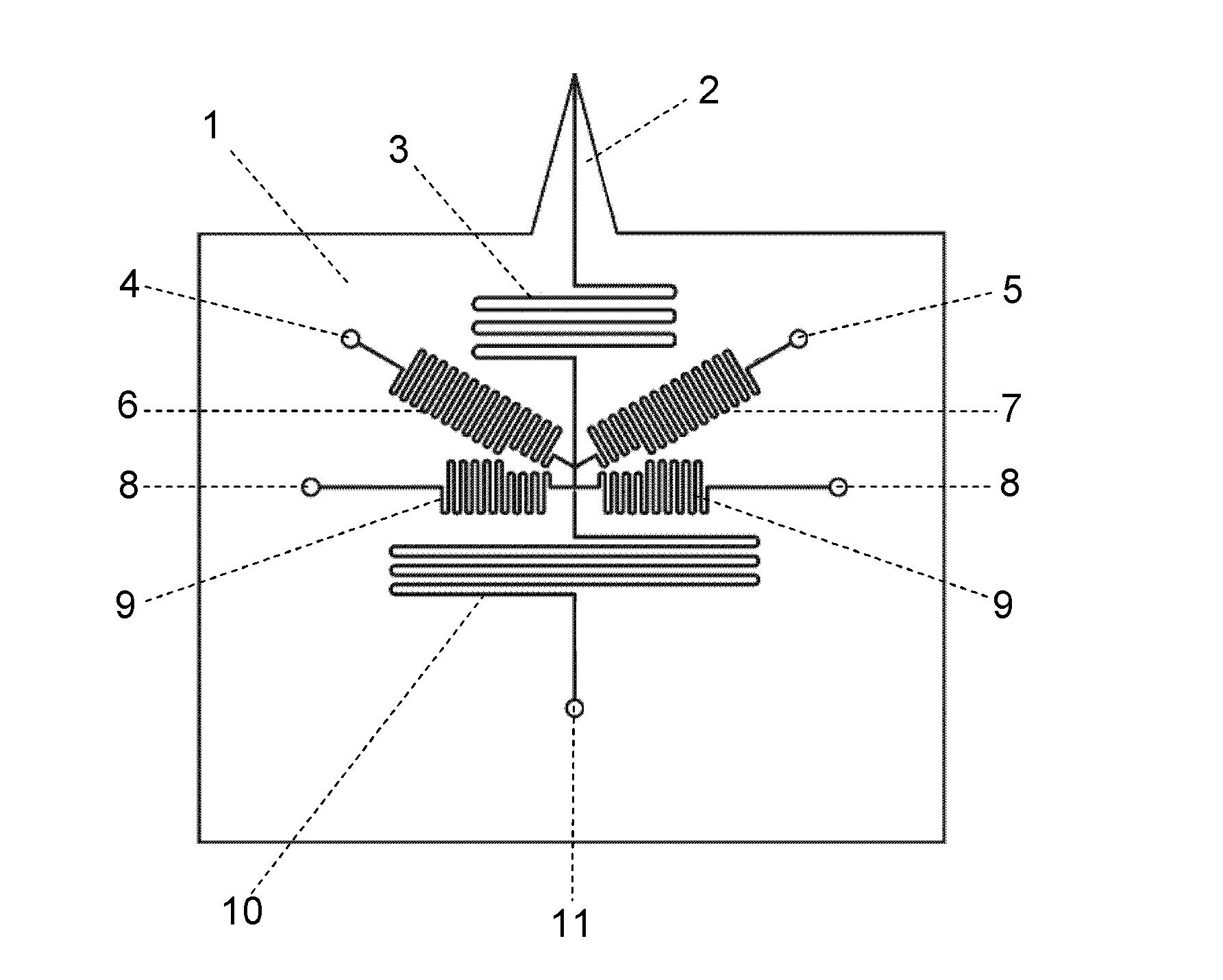
[0053] figure 1 It is a top view of the microfluidic concentration gradient droplet generation chip based on the flow injection gradient technology established according to the present invention. A sampling probe 2, a sample dispersion channel 3, a reagent channel 6 and a reagent channel 7, two immiscible phase channels 9, a droplet reaction and a detection channel 10 are processed on the chip substrate 1 by micromachining. The inlet end of the sample dispersing channel 3 is provided with a sampling probe 2, and the end of the sample dispersing channel 3 is connected with the outlet ends of the sample channels 6 and 7 and the outlet end of the immiscible phase channel 9 successively, and the sample dispersing channel 3 The outlet port of the droplet reaction and detection channel 10 is then communicated with the inlet port. The outlet end of the reagent channel 6 and the outlet end of the reagent channel 7 are arranged on both sides of the same cross-sectional position at the...

Embodiment 2

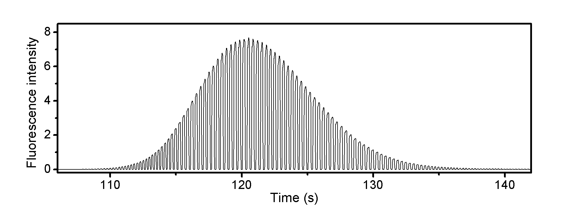
[0066] Figure 4 It is a recording chart of enzyme inhibition analysis results using the chip of Example 1 and taking a β-galactosidase inhibitor 2-phenylethyl-β-D-thiogalactoside (PETG) solution as a sample.

[0067] Specifically, 10mM tris(pH7.3) is used as carrier liquid, PETG solution is used as sample solution, β-galactosidase solution and substrate FDG solution are used to react with sample, tetradecane is used as immiscible phase.

[0068] The specific operation is as follows: the sampling probe 2 is inserted into a 10 mM tris (pH 7.3) solution containing a carrier liquid, and the sample dispersion channel is pre-filled with the carrier liquid. The two syringes used to drive the immiscible phase are filled with immiscible phase tetradecane and connected to the inlet port 8 of the immiscible phase channel 9 to provide positive pressure drive, and the immiscible phase tetradecane is injected into the immiscible phase channel 9 Inside, the immiscible phase channel 9 is f...


PUM

PropertyMeasurementUnit
Widthaaaaaaaaaa
Lengthaaaaaaaaaa

Abstract

The invention discloses a microfluidic concentration gradient droplet generating chip and a microfluidic concentration gradient droplet generating device. In the microfluidic concentration gradient droplet generating chip, a sample decentralizing channel, more than one reagent channel, more than one immiscible phase channel and a droplet reacting and detecting channel are processed on a chip base material processed by a quartz or organic solvent resistance material, a sampling probe integrated with the chip is processed at the inlet end of the sample decentralizing channel, the tail end of the sampling decentralizing channel is sequentially communicated with the outlet ends of the reagent channels and the outlet ends of the immiscible phase channel, and the outlet end of the sample decentralizing channel is communicated with the inlet end of the droplet reacting and detecting channel again. With the adoption of the microfluidic concentration gradient droplet generating device, a droplet array with the concentration gradient scope larger than three orders of magnitude can be formed by injecting a sample once, the consumption of the sample is less, and the generation of concentration gradient is quick. The microfluidic concentration gradient droplet generating device is especially suitable for high throughput screening research.

Description

1. Technical field: [0001] The invention relates to the field of microfluidic droplet analysis, in particular to a microfluidic concentration gradient droplet generation device and its use in a droplet generation method based on flow injection gradient and droplet microfluidic technology. 2. Background technology: [0002] Droplet-based microfluidic systems are an important research direction and hotspot in the field of microfluidics. It mainly divides a continuous fluid into discontinuous droplets under the action of immiscible carrier liquid through the design of microchannel network. Each droplet can be regarded as an independent microreactor because it is separated by the immiscible phase. The droplet-based microfluidic system solves the problems of slow mixing speed, low analysis throughput, and easy cross-contamination in the continuous flow-based microfluidic system, and further reduces the consumption of reagents and samples. In addition, the advantages of micro-dr...

Claims


Application Information

Patent Timeline
IPC IPC(8): B01L3/00G01N35/08
Inventor 方群蔡龙飞祝莹
Owner ZHEJIANG UNIV
Why Eureka
Try Eureka