
Tooling for stamping production line

An end picker and production line technology, applied in metal processing equipment, feeding devices, manufacturing tools, etc., can solve the problems of reducing the production efficiency of high-speed lines, increasing the scrap rate of stamping parts, and stopping the production line, so as to meet the requirements of high-speed production. The effect of demand, low production cost and short action time

Active Publication Date: 2014-12-10
CHERY AUTOMOBILE CO LTD
View PDF8 Cites 2 Cited by
  • Summary
  • Abstract
  • Description
  • Claims
  • Application Information

AI Technical Summary

Problems solved by technology

[0003] In the stamping parts, due to the complex shape of some large covering parts, such as the inner panel of the hair cover and the inner panel of the trunk lid, etc., there are many punching holes, and the upper plane area of ​​the punched part is small; therefore, the model has to be used. Smaller suction cups are used to suck stamping parts, and the use of small suction cups will cause problems for the automatic production of stamping parts: usually, the mechanical arm is faster in the process of lateral transmission between the front and back of the stamping parts, and the smaller suction cups The shear force received is greater than its maximum suction force, and the suction cup cannot hold the stamped parts, which may easily lead to the occurrence of dropped parts, resulting in the deformation of the parts and the shutdown of the production line, which not only reduces the production efficiency of the high-speed line, but also increases the number of stamped parts. scrap rate

Method used


Image

  • Tooling for stamping production line
  • Tooling for stamping production line
  • Tooling for stamping production line

Examples


Embodiment Construction

[0025] The specific implementation manner of the present invention will be described in further detail below by describing the best embodiment with reference to the accompanying drawings.

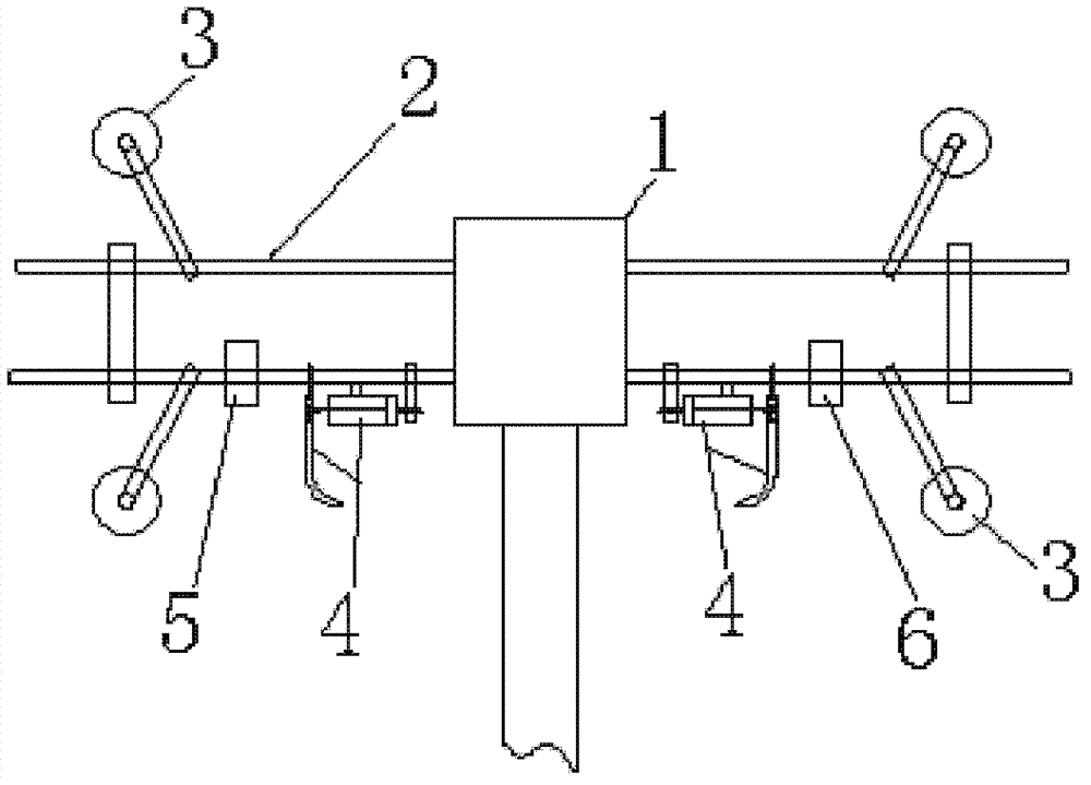
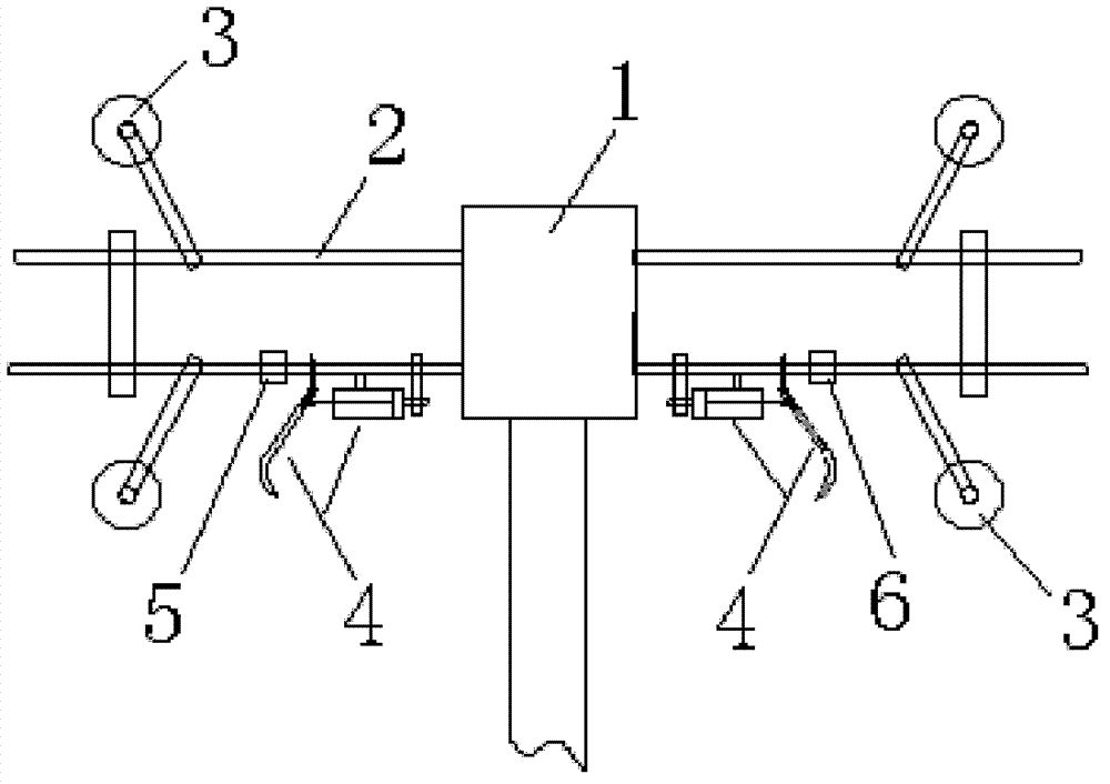
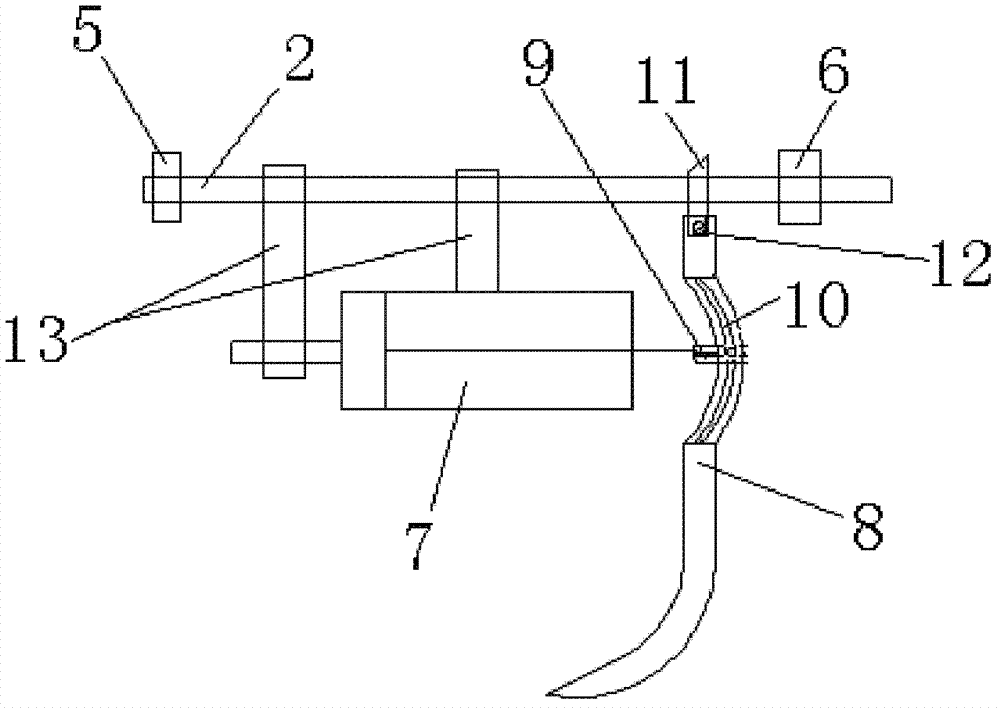
[0026] like Figure 1 to Figure 4 As shown, the end picker used in the stamping production line includes the end picker cross bar 2 connected with the mechanical arm 1 in the middle, the end picker cross bar 2 is provided with a suction cup 3, and the end picker cross bar 2 is located on the mechanical Both sides of the arm 1 are respectively provided with grabbing mechanisms 4, and the grabbing mechanisms are arranged symmetrically with the mechanical arm 1 as the center of symmetry. The position close to the mechanical arm 1 on the cross bar 2 of the end picker can ensure the mechanical strength of the end picker and reduce the bending moment load of the grab mechanism 4 on the cross bar 2 of the end picker; The cylinder 7 connected to the pickup bar 2 and the gripper 8 located on one si...


PUM


Abstract

The invention discloses a tooling for a stamping production line, which comprises a tooling cross rod; the middle of the tooling cross rod is connected with a mechanical arm; a sucker is arranged on the tooling cross rod; grabbing mechanisms are respectively arranged on positions on two sides of the mechanical arm and on the tooling cross rod; each grabbing mechanism comprises an air cylinder which is connected with the tooling cross rod, and a clamping jaw which is arranged at one side of each air cylinder; one end of each camping jaw is connected with the tooling cross rod in a movable way; the other end of the clamping jaw is a workpiece clamping end with radian; the clamping jaws are connected with piston rods of the air cylinders; the connecting positions of the clamping jaws and the piston rods of the air cylinders are close to the ends of the clamping jaw ends connected with the tooling cross rod; each air cylinder is connected with an air pipe interface of the mechanical arm by an air pipe; and an electrical signal interface of the air cylinders and the mechanical arm are respectively connected on a terminal box arranged on the tooling cross rod. The grabbing mechanisms in the tooling can assist the sucker to clamp a workpiece, so that the workpiece is not likely to slide off, the stamping production efficiency can be ensured, and simultaneously the yield of stamping parts can be ensured.

Description

technical field [0001] The invention relates to automatic equipment on an automatic stamping production line, in particular to an end picker used in the stamping production line. Background technique [0002] With the rapid development of the automobile industry, in order to improve production efficiency, major automobile manufacturers have begun to use high-speed automated stamping production lines to complete the production of stamping parts on a large scale. At present, the end picker used on the high-speed automatic production line includes the end picker cross bar connected with the mechanical arm and the suction cup on the end picker cross bar. The suction cup is the main working part, and the function of the suction cup is to suck the stamping parts. , and then the transfer of stamping parts is realized by the movement of the mechanical arm. [0003] In the stamping parts, due to the complex shape of some large covering parts, such as the inner panel of the hair cove...

Claims


Application Information

Patent Timeline
Patent Type & Authority Patents(China)
IPC IPC(8): B21D43/10
Inventor 柴延青胡辉方孝安刘玲
Owner CHERY AUTOMOBILE CO LTD
Learn More