
Milling finish machining method based on dynamic rigidity of impeller blade

An impeller blade, dynamic stiffness technology, applied in the field of machining, can solve problems such as the importance of suppression not involved, achieve the effect of improving machining stability and solving cutting chatter

Active Publication Date: 2014-02-26
SHANGHAI JIAO TONG UNIV
View PDF9 Cites 0 Cited by
  • Summary
  • Abstract
  • Description
  • Claims
  • Application Information

AI Technical Summary

Problems solved by technology

A common feature of the above patents is that they do not involve the importance of suppressing cutting chatter during blade machining, and start to solve the problem from the direction of blade dynamic stiffness and cutting parameter optimization, only emphasizing the influence of numerical control and cutting tools

Method used


Image

  • Milling finish machining method based on dynamic rigidity of impeller blade
  • Milling finish machining method based on dynamic rigidity of impeller blade
  • Milling finish machining method based on dynamic rigidity of impeller blade

Examples


Embodiment Construction

[0017] The content of the milling finishing method based on the dynamic stiffness of the impeller blade according to the present invention is to obtain the dynamic mode (damping ratio, stiffness, natural frequency, effective mass) of the impeller blade through the standard modal test, and then introduce flutter The model can be used to obtain the stability criterion, so as to obtain reasonable processing parameters.

[0018] The present invention will be further described below in conjunction with the accompanying drawings, and the details of each step will be set forth.

[0019] Processing method of the present invention comprises the steps:

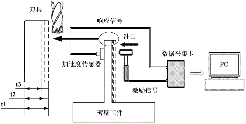
[0020] Step 1: Modal test to determine the dynamic mode of the impeller blade: the principle is as follows figure 1 As shown in , the standard hammer impact test is adopted, by collecting the impact excitation signal of the hammer and the response signal of the acceleration sensor, aiming at the changing wall thickness t 1 , t 2 and ...


PUM


Abstract

The invention discloses a milling finish machining method based on the dynamic rigidity of an impeller blade. The dynamic modality of the impeller blade is obtained through a standard modal test, a flutter model is introduced to obtain a stability criterion, and reasonable machining parameters are acquired. The method comprises the followings steps of: 1, performing the modal test to measure the dynamic modality of the impeller blade; 2, building a milling stability model of the impeller blade; 3, studying the dynamic rigidity stability of the impeller blade; 4, obtaining a cutting stability condition under the dynamic rigidity of the impeller blade; and 5, verifying the cutting stability condition and adopting the finally optimized cutting parameters to machine. The problem of cutting flutter caused by milling of thin-walled parts such as the blade is solved by the method, and the machining stability is obviously improved by optimizing the cutting parameters. The method is suitable for finish machining of various thin-walled parts.

Description

technical field [0001] The invention relates to a processing method for impeller blades, in particular to a milling and finishing method for thin-walled parts considering dynamic stiffness, and belongs to the technical field of mechanical processing. Background technique [0002] The impeller blade is a very typical and representative thin-walled part, which is widely used in aerospace, metallurgy, military industry, petrochemical, electric power and other fields. It is the core component of fans, engines, compressors, water pumps and other machinery. The quality of blade processing and whether the processing accuracy meets the requirements directly determine the performance of the entire equipment. In the manufacture of impeller blades, due to the characteristics of thin blades and long blade spans, tools with a large aspect ratio are usually used. However, this will cause a contradiction between the weak rigidity of the process system and the strong input excitation during...

Claims


Application Information

Patent Timeline
Patent Type & Authority Patents(China)
IPC IPC(8): B23C3/00G06F17/50
Inventor 陈明董大鹏李军利牛秋林安庆龙
Owner SHANGHAI JIAO TONG UNIV
Learn More