
Integral copper crucible and method for producing copper crucible by integral forging and rotary pressing

An integral forging and copper crucible technology, which is applied in crucible furnaces, manufacturing tools, metal processing equipment, etc., can solve the problems of high tension at the joints, differences in thermal expansion coefficients, high cost and price, and achieve improved strength, good quality, and machine processing. The effect of fee reduction

Inactive Publication Date: 2012-07-11
陈普选
View PDF1 Cites 5 Cited by
  • Summary
  • Abstract
  • Description
  • Claims
  • Application Information

AI Technical Summary

Problems solved by technology

[0010] In the patent text disclosed by the patent CN2757077Y, it is stated that "copper ingots or large-diameter copper rods are forged and spun to make blanks, which are made by machining. The cylinder and flange are an integral structure without any welds. It not only guarantees the overall quality of the crucible”, it can be seen from the above that its processing technology uses a whole piece of copper ingot or large-diameter copper rod, and then the outer edge surface is pre-forged and cut on the copper ingot or large-diameter copper rod to obtain the inner hole and flange. The plate is formed into a blank, and then dipped in fire, heated and hot-rolled. This process requires repeated dipping in fire, heated and hot-rolled in this field; Copper crucibles have undetectable cracks or fractures, which are difficult to detect through flaw detection. Of course, the amount of material fed into the copper crucible is large, the manufacturing is difficult, and the cost price is relatively high; there is also a large difference in thermal expansion coefficient during use, resulting in joints. Withstand high and frequent tension

Method used


Image

  • Integral copper crucible and method for producing copper crucible by integral forging and rotary pressing
  • Integral copper crucible and method for producing copper crucible by integral forging and rotary pressing
  • Integral copper crucible and method for producing copper crucible by integral forging and rotary pressing

Examples


Embodiment Construction

[0037] The present invention is further described below in conjunction with embodiment; The following embodiment is not for the limitation of the present invention, only as the mode of supporting the realization of the present invention, any equivalent structural replacement within the technical framework disclosed in the present invention, all is the present invention. the scope of protection of the invention;

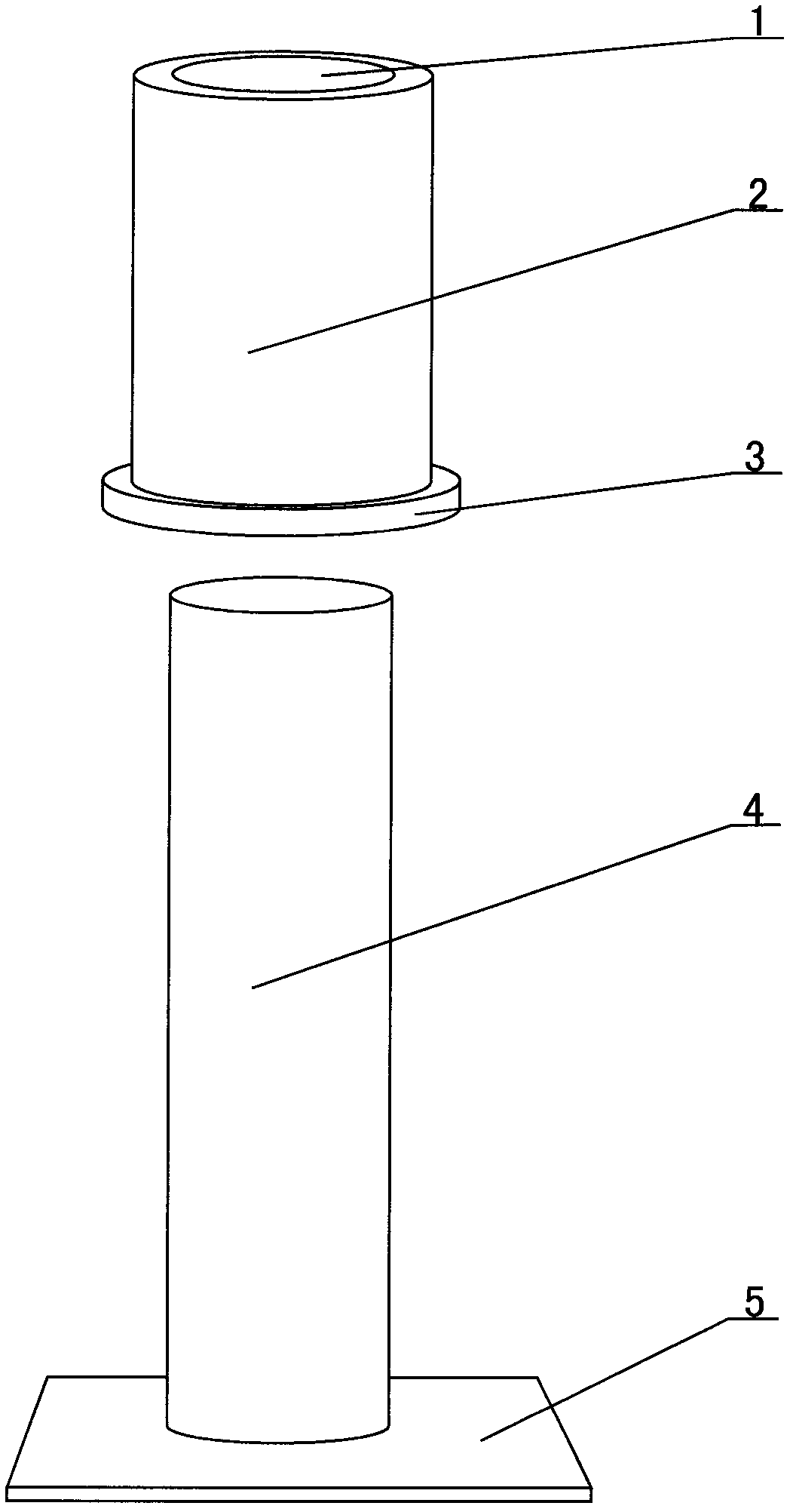
[0038] combined with Figure 5 The described integral copper crucible comprises a cylindrical body 2 and a flange 3, the cylindrical body 2 is a circular structure, and a flange 3 is arranged at one end of the circular structure cylindrical body 2, and the flange is 3 and the cylinder body 2 are a seamless integral structure, and a through inner hole 1 is provided from one end of the flange plate 3 of the cylinder body 2 to the other end of the cylinder body 2, and the inner hole 1 is circular with the same diameter.

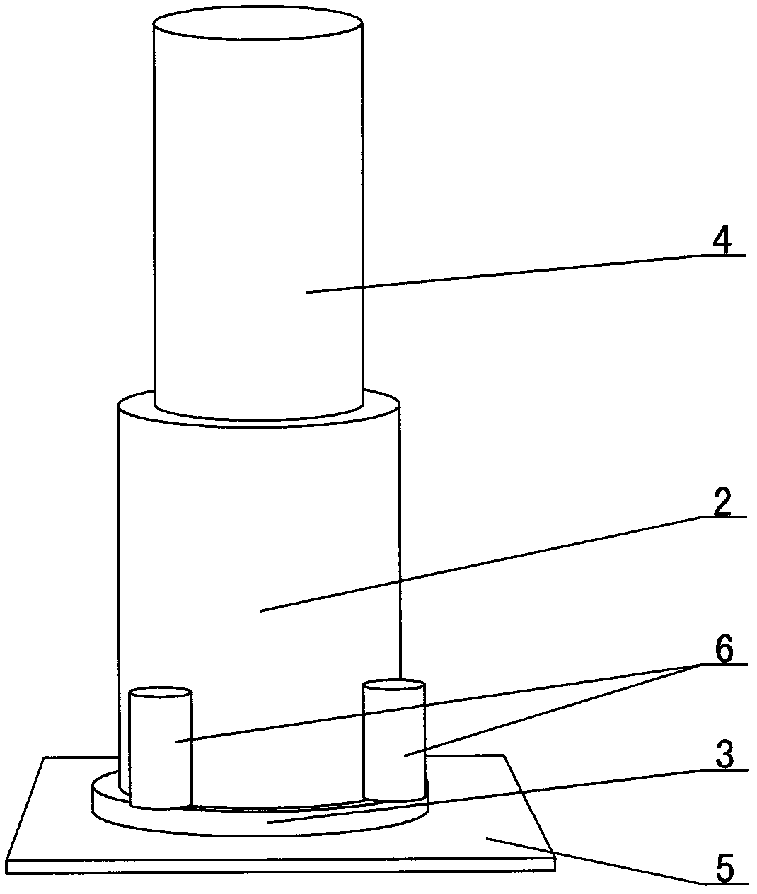
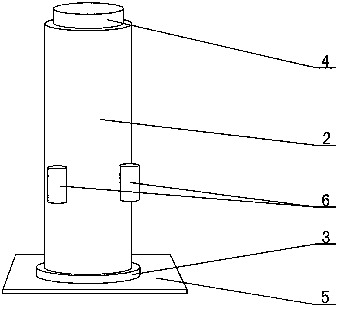
[0039] combined with Figure 1~4 The method for...


PUM


Abstract

The invention discloses an integral copper crucible and a method for producing the copper crucible by integral forging and rotary pressing, and relates to a copper crucible and a machining method. A barrel (2) has a circular structure; one end of the barrel (2) with the circular structure is provided with a flange plate (3); the flange plate and the barrel are integrated; and an inner through hole (1) with the same hole diameter is formed from one end of the barrel, which is provided with the flange plate (3), to the other end of the barrel (2). Rotary pressing equipment is involved in the method for producing the copper crucible, and a blank is uniformly pressed by a mandrel (4) and a rotary pressing mechanism and is deburred and ground to form the copper crucible. By the method for machining the copper crucible by integral forging, the finished copper crucible does not have any weld joint, the defect of unperceivable cracks or rupture at the later stage of using the copper crucible is effectively overcome, and raw material cost, forging cost and machining cost are greatly reduced.

Description

【Technical field】 [0001] The invention relates to a copper crucible and a processing method, in particular to an integral copper crucible and a method for producing the copper crucible by integral forging and spinning. 【Background technique】 [0002] It is known that vacuum consumable electric arc furnaces and electroslag furnaces are widely used in the industry to smelt titanium, molybdenum, tantalum, niobium, zirconium and other rare metals and special steel processing; copper crucible "also called: copper crystallizer" is One of the important parts of vacuum consumable electric arc furnace and electroslag furnace. The existing copper crucible includes two parts: a cylinder and a flange. The copper crucible cylinder, and then the flange is welded on the outer edge of the cylinder to form a copper crucible. Since the copper crucible is used in a vacuum and high temperature environment, the copper crucible must have a seamless or integral structure, which can not only overc...

Claims


Application Information

Patent Timeline
Patent Type & Authority Applications(China)
IPC IPC(8): C22B9/193F27B14/10B23P15/00B21D22/16B21D37/16B21J5/00B21J5/10
Inventor 陈普选胡宗式
Owner 陈普选
Learn More