Rotating cathode mechanism

A technology of rotating cathode and rotating mechanism, applied in ion implantation plating, metal material coating process, coating, etc., can solve the problems of low utilization rate, fast consumption speed, uneven consumption of target materials, etc., and achieve improved utilization rate , good uniformity, reducing the effects of arcing and target surface slag

Inactive Publication Date: 2012-07-11
WUXI KANGLI ELECTRONICS
View PDF3 Cites 2 Cited by
  • Summary
  • Abstract
  • Description
  • Claims
  • Application Information

AI Technical Summary

Problems solved by technology

[0005] The purpose of the present invention is to solve the problems of uneven target material consumption, low utilization rate and fast consumption rate in existing sputtering targets, and propose a new type of rotating cathode mechanism. By rotating the target material during the sputtering process, the The consumption of the target in the whole area can be etched evenly, and the primary utilization rate of the target can be increased to more than 80%; at the same time, it can effectively reduce arcing and slag on the target surface, and the process stability is good

Method used


Image

  • Rotating cathode mechanism
  • Rotating cathode mechanism
  • Rotating cathode mechanism

Examples


Embodiment Construction

[0023] The present invention will be further described below in conjunction with the accompanying drawings and embodiments.

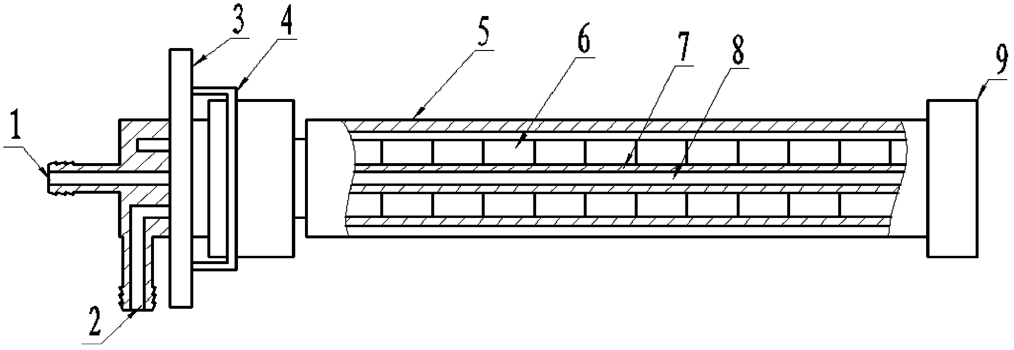
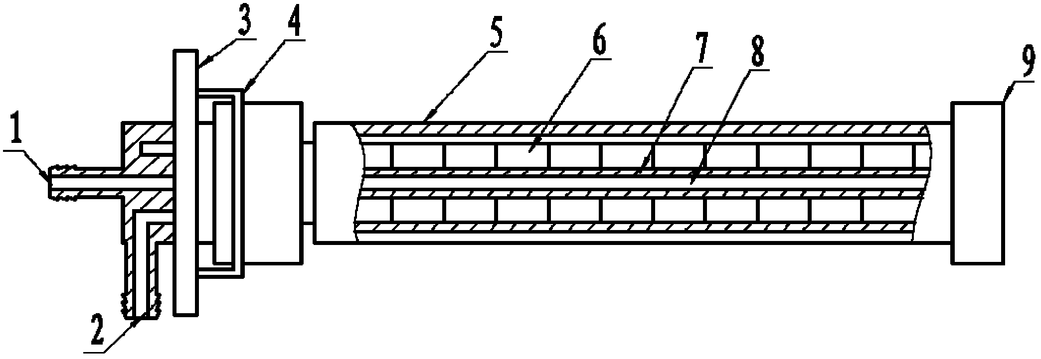
[0024] Such as figure 1 As shown, a rotating cathode mechanism includes a target rotating mechanism 4, a target bracket 3, a cooling water pipe 8, a pole shoe 7 installed outside the cooling water pipe 8, a plurality of bar magnets 6, a target material 5, and the sleeve One end cover 9 is installed on one side, the target rotation mechanism 4 and the target bracket 3 are installed on the other end, and a stainless steel tube is set between the bar magnet 6 and the target material 5 .

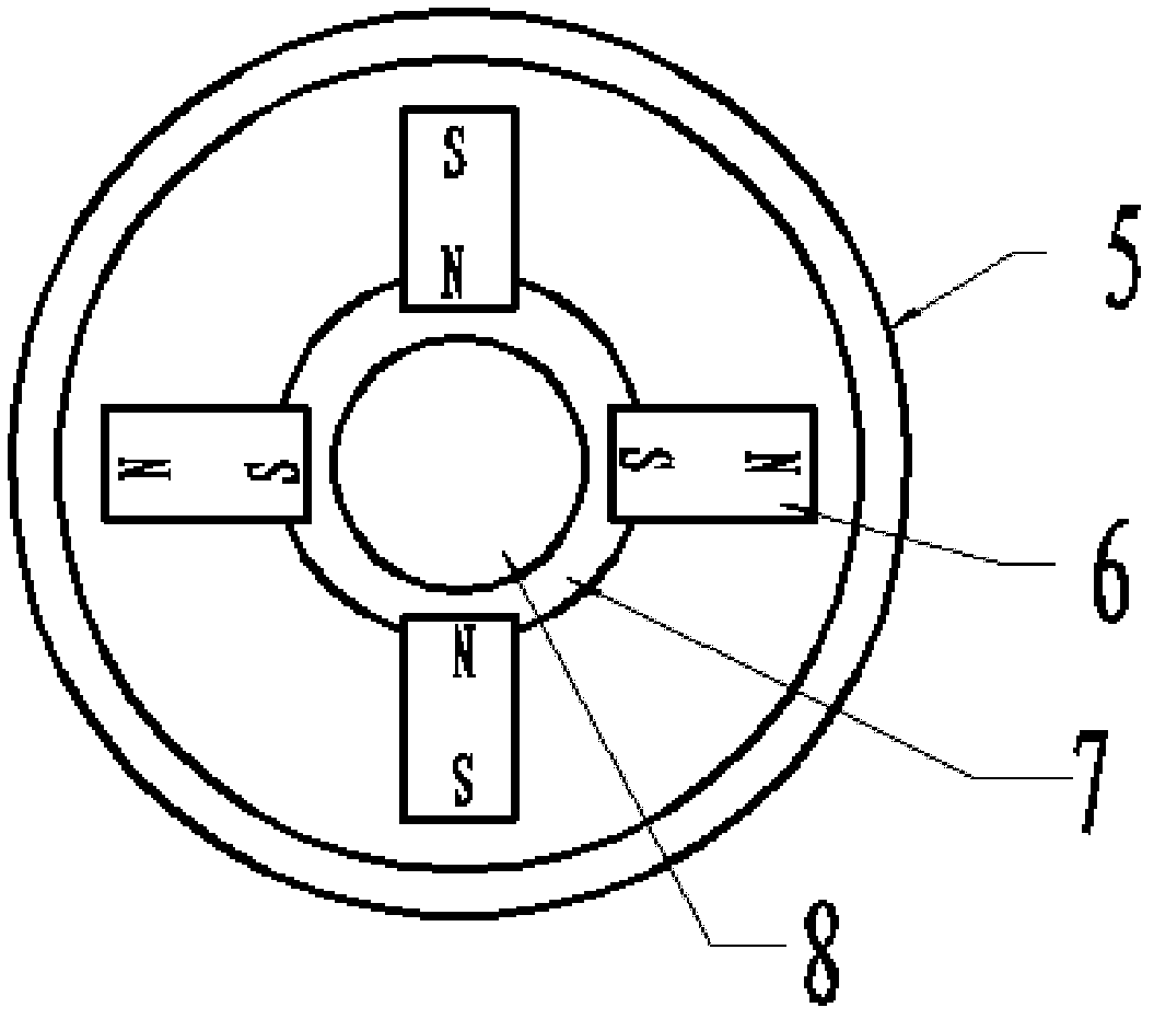
[0025] The outer side of the pole piece 7 of the present invention is provided with a plurality of positioning grooves, and a plurality of corresponding bar magnets 6 are installed in the positioning grooves of the pole piece 7 respectively; figure 2 As shown, the combination of the bar magnets 6 is that the direction of each bar magnet is the same, and they are arrange...


PUM


Abstract

The invention relates to a rotating cathode mechanism which comprises a target rotating mechanism (4), a target bracket (3), a cooling water pipe (8), a pole boot (7), a plurality bar-shaped magnets (6) and a target material (5), wherein the pole boot (7), the plurality bar-shaped magnets (6) and the target material (5) are mounted outside the cooling water pipe (8) in sequence; an end cover (9) is mounted on one side of a sleeve; the target rotating mechanism (4) and the target bracket (3) are mounted at the other end of the sleeve; and a stainless steel tube is sleeved between the bar-shaped magnets (6) and the target material (5). The rotating cathode mechanism is a novel mechanism; the target material is rotated during a sputtering process, so that the consumption of the target material in the whole area is utilized to uniformly etch and the once use ratio of the target material is increased to above 80%; and the arcing and target surface residues are efficiently reduced and the stability of the technology is excellent.

Description

technical field [0001] The invention relates to a sputtering coating process, in particular to a cathode used for sputtering in the frequency sputtering coating process, that is, a sputtering target, in particular to a rotating cathode mechanism. [0002] Background technique [0003] At present, the two cathodes (also called sputtering targets) commonly used for sputtering in the intermediate frequency sputtering coating process are usually two side-by-side planar targets with the same size and shape. These two targets are often called twin targets. The twin targets are suspended in the sputtering chamber, and the two targets take turns as cathode and anode periodically during the sputtering process. Since the working mode of the sputtering target used is fixed, the shape of the consumption of the sputtering target is proportional to the sine value of the magnetic field, which will form an etching shape with a wide top and a narrow bottom, making the consumption of the ta...

Claims


Application Information

Patent Timeline
Patent Type & Authority Applications(China)
IPC IPC(8): C23C14/34
Inventor 朱殿荣曹俊
Owner WUXI KANGLI ELECTRONICS
Why Eureka
Try Eureka