Compound fertilizer generation system

A technology for generating a system and compound fertilizer, applied in fertilization devices, fertilizer mixtures, applications, etc., can solve the problems of difficult control of the reaction process, uneven particles, and low product strength, and achieve easy control of the reaction process, uniform particle size, one-time The effect of high utilization

Inactive Publication Date: 2018-08-24
HUBEI UNIV OF TECH
View PDF4 Cites 0 Cited by
  • Summary
  • Abstract
  • Description
  • Claims
  • Application Information

AI Technical Summary

Problems solved by technology

[0007] (1) The acid needs to be mixed in the acid mixing tank before the acid is sent to the granulator, which will generate a lot of heat, troublesome operation, and potential safety hazards;
[0008] (2) The moisture content is still greater than 5%, resulting in high subsequent drying pressure, the final product is easy to agglomerate, the particles are uneven, the product strength is low (usually 20-25N), the return rate is high, and the return rate can reach 20-25% , the production efficiency is low;
[0009] (3) Due to the high moisture content of the material, it is usually necessary to add additional binders (such as clay) to ensure the granulation rate, which not only costs a lot, but also reduces the water solubility of the product;
[0010] (4) The tail gas treatment section will produce a large amount of washing liquid, which cannot be used;
[0011] (5) The reaction process is difficult to control, resulting in large differences between batches of products

Method used


Image

  • Compound fertilizer generation system
  • Compound fertilizer generation system
  • Compound fertilizer generation system

Examples


Embodiment Construction

[0030] Below in conjunction with accompanying drawing, the present invention will be further explained:

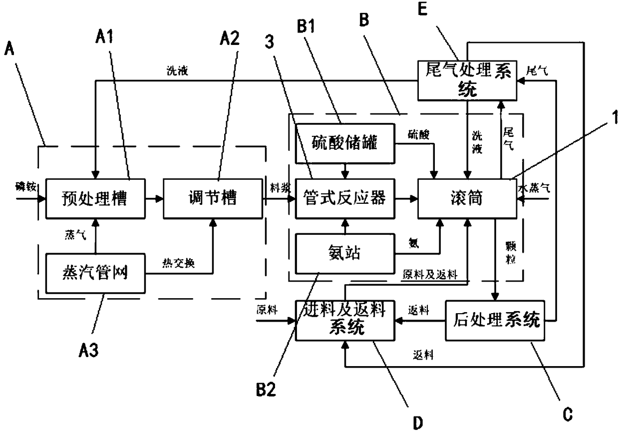
[0031] see figure 1 , the embodiment of the present invention provides a compound fertilizer production system, the system includes a pretreatment system A, a granulation system B, a post-treatment section C, a feed and return system D, and an exhaust gas treatment system E, wherein the pretreatment system A, granulation system B, post-processing system C and feed and return system D are sequentially connected, the granulation system B and post-processing system C are also connected to the tail gas treatment system E, and the generated tail gas is uniformly sent to the tail gas treatment System E does the processing.

[0032] The connection relationship and process flow of each equipment in the post-processing section C, the feeding and returning system D, and the tail gas treatment system E are the same as those of the prior art, and those skilled in the art can also rea...


PUM


Abstract

The invention discloses a compound fertilizer generation system, and solves the problems of uneven particle, high moisture content, more returning charge and the like in the production and granulationprocesses of the existing compound fertilizer. In the technical scheme, the compound fertilizer generation system comprises a pretreatment system, a granulation system, a posttreatment system and a charge and returning charge system which are sequentially connected, the granulation system comprises a roller provided with a drive device, a discharge structure is connected to the rear end of the roller, a charge tube, an acid mixing tube, a tubular reactor and an ammonia spraying tube bundle are sequentially arranged at the front section of the roller from top to bottom, the acid mixing tube, the tubular reactor and the ammonia spraying tube bundle are respectively provided with a sprayer; the charge tube is connected with the charge and returning charge system, the tubular reactor is connected with an ammonia station, the pretreatment system and a sulfuric acid storage tank respectively; the acid mixing tube is connected with a tail gas treatment system and the sulfuric acid storage tank respectively; and the ammonia spraying tube bundle is connected with the ammonia station. The system is simple, saves energy and reduces consumption, the product strength is high, the returning rate is low, the production efficiency is high, the water solubility is good, and the compound fertilizer generation system is environmentally friendly.

Description

technical field [0001] The invention belongs to the technical field of compound fertilizer production, and in particular relates to a compound fertilizer generating system using a double ammonia half slurry method. Background technique [0002] The production of compound fertilizer includes processes such as granulation, drying, cooling, screening, coating and bagging. Tail gas will be generated during the process of granulation, drying and cooling. Therefore, the compound fertilizer production system usually includes a granulation system, a post-treatment system , Exhaust gas treatment system and feeding and returning system. The post-processing section includes drying, cooling, screening, coating and bagging, etc. The tail gas treatment section is used for tail gas treatment, and the feeding and returning section is used for feeding and returning material. Among them, the granulation can use a drum granulator to granulate sulfuric acid, ammonia, potassium fertilizer, phos...

Claims


Application Information

Patent Timeline
Patent Type & Authority Applications(China)
IPC IPC(8): C05G1/00
CPCC05G1/00
Inventor 廖斌简永超
Owner HUBEI UNIV OF TECH
Why Eureka
Try Eureka