Magnetic control sputtering equipment

A magnetron sputtering and equipment technology, applied in the field of magnetron sputtering equipment, can solve the problems of multiple equipment space, occupation, increase the volume of the process chamber, etc., to save operating costs, save processing costs, and reduce equipment volume. Effect

Inactive Publication Date: 2012-07-11
BEIJING NAURA MICROELECTRONICS EQUIP CO LTD
View PDF3 Cites 15 Cited by
  • Summary
  • Abstract
  • Description
  • Claims
  • Application Information

AI Technical Summary

Problems solved by technology

[0008] Second, during the normal magnetron sputtering process, in order to avoid the impact of components such as the shielding plate on the process quality, it is necessary to keep the above components away from the area where the electrostatic chuck is located, which requires a set in the process chamber. The storage area shown in 2 is specially used to place the above-mentioned shielding plate and other components. Therefore, it will inevitably increase the volume of the process chamber, which will not only occupy too much equipment space, but also increase a lot of equipment processing costs and operating costs.
[0009] Third, although when the above-mentioned magnetron sputtering equipment is performing the sputtering process, the above-mentioned components such as the shielding disk used to shield the electrostatic chuck are located away from the electrostatic chuck, the space for storing the above-mentioned shielding disk and other components is different from that of the electrostatic chuck. The area where the electrostatic chuck is located belongs to the inner space of the process chamber, so it is very likely to affect the distribution of the airflow field and temperature field in the process chamber, and ultimately affect the process quality

Method used


Image

  • Magnetic control sputtering equipment
  • Magnetic control sputtering equipment
  • Magnetic control sputtering equipment

Examples


Embodiment Construction

[0028] In order to enable those skilled in the art to better understand the technical solution of the present invention, the magnetron sputtering equipment provided by the present invention will be described in detail below with reference to the accompanying drawings.

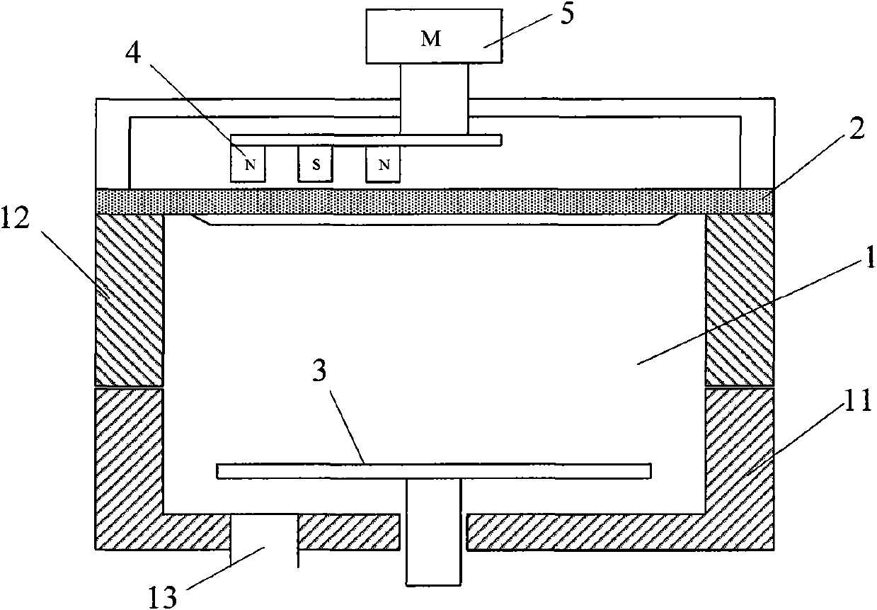
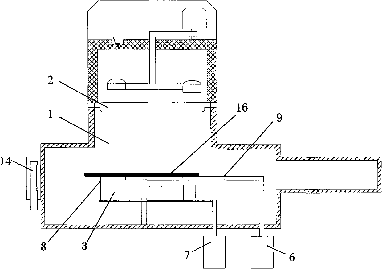
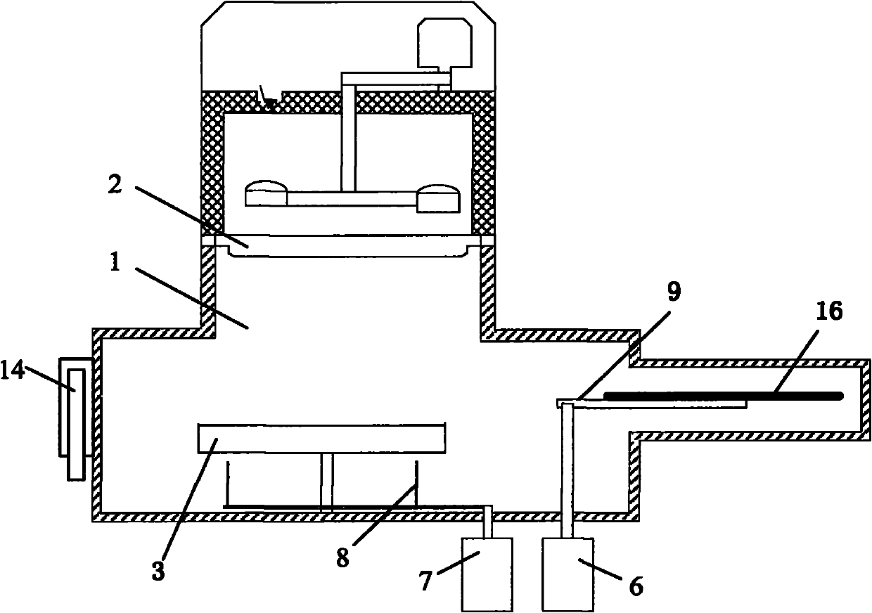
[0029] The magnetron sputtering equipment provided by the present invention includes at least one process chamber, a target and a substrate carrying device arranged inside the process chamber; in addition, it also includes at least one shielding plate. When removing the oxide on the surface of the target material, the substrate carrying device is protected by means of the above-mentioned shielding disc to prevent the fallen oxide particles from falling on the surface of the substrate carrying device and causing pollution; and, after removing the target material oxide, the The shielding disk is stored outside the process chamber. In a specific embodiment, the above-mentioned magnetron sputtering equipment furthe...


PUM


Abstract

The invention provides magnetic control sputtering equipment which comprises at least one process cavity, a target material, a substrate bearing device and at least one shielding disc, wherein the target material and the substrate bearing device are arranged at the inner part of the process cavity, and the shielding disc is stored at the outer part of the process cavity. When the oxide on the surface of the target material is removed, the shielding disc is transferred to the inner part of the process cavity so as to protect the substrate bearing device from being polluted. According to the magnetic control sputtering equipment, the shielding disc is stored at the outer part of the process cavity, so that the inner structure and the volume of the process cavity can be effectively simplified, and the shielding disc can be shared by a plurality of process cavities, so that the equipment processing and running cost can be reduced effectively; and the influence on the process environment caused by the shielding disc and a driving device of the shielding disc can be avoided, thereby being benefit to the acquisition of the better process quality.

Description

technical field [0001] The invention relates to the technical field of microelectronic processing, in particular to a magnetron sputtering device. Background technique [0002] With the continuous advancement of integrated circuit production technology, the integration level of circuit chips has been greatly improved. At present, the number of transistors integrated in a chip has reached an astonishing tens of millions, and the signal integration of such a large number of active components requires more than ten layers of high-density metal interconnection layers for connection. Therefore, as an important process for preparing the above-mentioned metal interconnection layer, physical vapor deposition (Physical Vapor Deposition, hereinafter referred to as PVD) technology has been widely used. [0003] In the semiconductor manufacturing industry, PVD generally refers to the thin film preparation process that uses physical methods to prepare thin films; in the integrated circu...

Claims


Application Information

Patent Timeline
Patent Type & Authority Applications(China)
IPC IPC(8): C23C14/35C23C14/56
Inventor 夏威
Owner BEIJING NAURA MICROELECTRONICS EQUIP CO LTD
Why Eureka
Try Eureka