Completion reoperation blowout control tail tube valve

A technology of blowout prevention and tailpipe, which is applied in the direction of wellbore/well valve device, flushing wellbore, wellbore/well parts, etc., which can solve the problem of clogging of the inner hole of the tubing well bottom, difficulty in delivering pluggers, and long operating cycle. Long-term problems, to achieve the effect of reducing operating costs, eliminating potential damage and safety hazards of operations, and convenient on-site operation

Inactive Publication Date: 2012-07-11
JIANGSU XINCAIYANG ELECTROMECHANICAL TECH
View PDF0 Cites 9 Cited by
  • Summary
  • Abstract
  • Description
  • Claims
  • Application Information

AI Technical Summary

Problems solved by technology

[0004] The purpose of the present invention is to provide a method that overcomes the above-mentioned shortcomings of the prior art, and solves the problem of blockage of the inner hole of the tubing well bottom during the pressurized operation of the pressurized oil and gas well, difficulty in delivery of the plug, low success rate of one delivery, and long operation period. A kind of blowout preventer tailpipe valve for well completion and reoperation that can simplify plugging construction of the original well preset tool for the problem of high cost;

Method used


Image

  • Completion reoperation blowout control tail tube valve
  • Completion reoperation blowout control tail tube valve
  • Completion reoperation blowout control tail tube valve

Examples


Embodiment Construction

[0024] An embodiment of the present invention is described in detail below in conjunction with accompanying drawing:

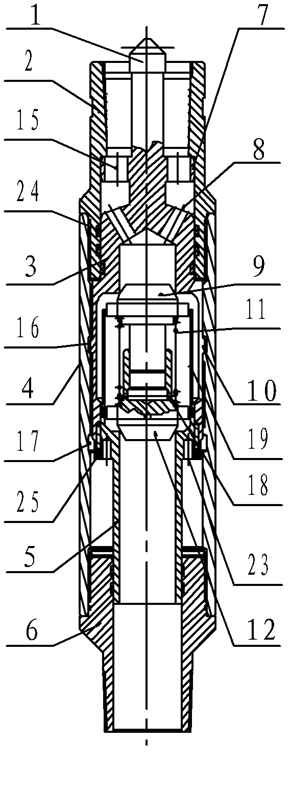
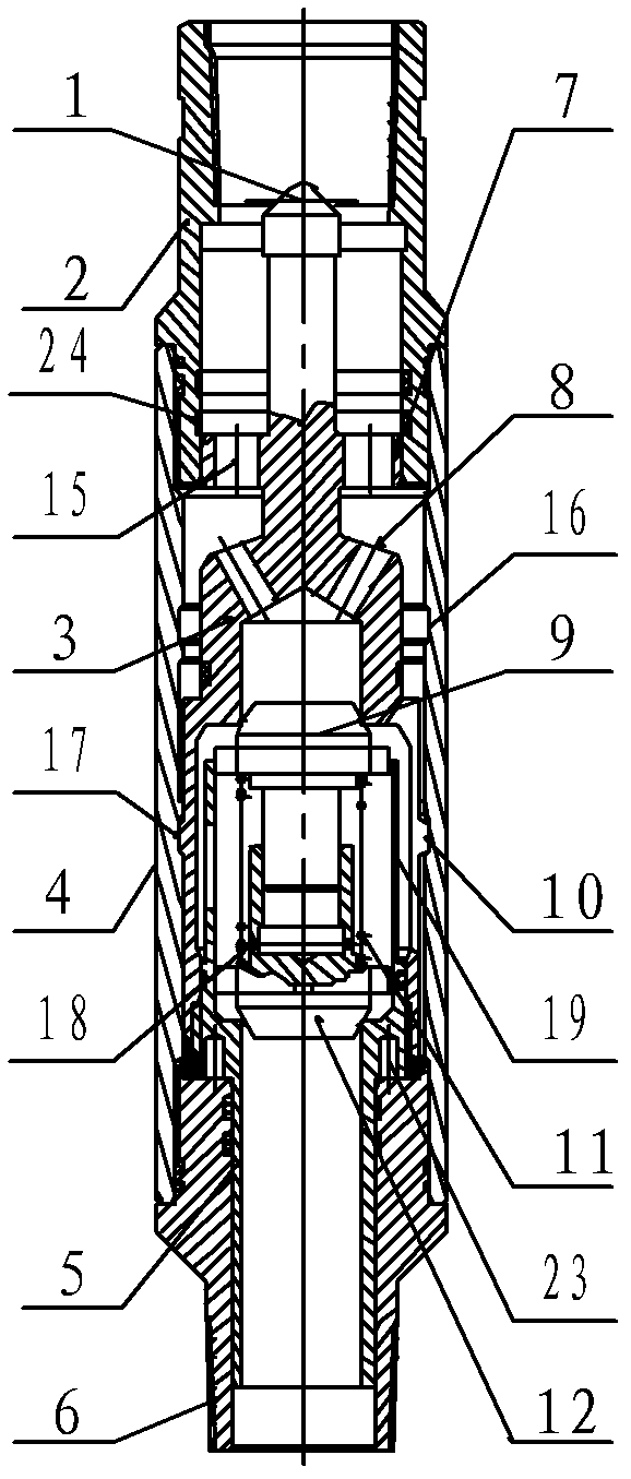
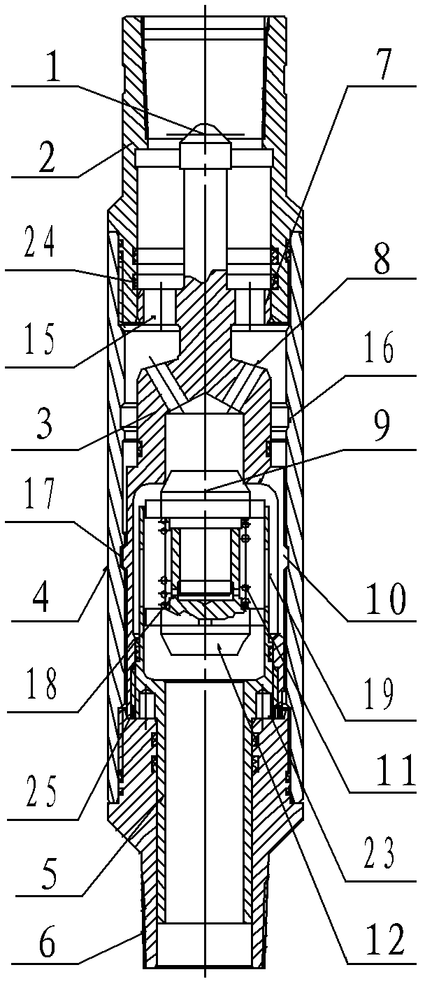
[0025] Such as figure 1 , Figure 5 , Image 6 As shown, the valve is connected with the upper joint 2 and the lower joint 6 respectively in the inner holes of the upper and lower ends of the coupling 4 to form the valve body shell, and the inner hole of the upper joint 2 is provided with a cone connected to the tail of the oil pipe. Shaped connecting screw hole, the lower end of the lower joint 6 is provided with a tapered threaded joint connected to the outer periphery of the screen pipe, and the inner hole of the valve is formed under the tapered connecting screw hole, the lower end surface of the upper joint 2 and the lower end surface of the lower joint 6. The three-stage positioning step through hole on the upper end surface, the inner hole of the valve body and the inner hole wall of the coupling 4 are provided with an upper limit groove 16 and a lowe...


PUM


Abstract

The invention relates to a completion reoperation blowout control tail tube valve. The completion reoperation blowout control tail tube valve is characterized in that an upper joint and a lower joint are respectively assembled in inner holes of the upper end and the lower end of a coupling to form a valve body shell; an upper valve seat is assembled in a valve body, a step type downward opening blind hole with the small upper end and the large lower end is arranged in an upper valve seat body, the lower end of the blind hole is a screw hole, and a valve seat elastic claw which is in the shape of a lantern framework is arranged on the inner hole wall of the upper portion of the screw hole of the large step hole; a plurality of flow guiding holes communicated with the blind hole are arranged on the upper portion of the upper valve seat; a lower valve seat is in the shape of a hollow step shaft, the lower end of the upper portion of the lower valve seat is assembled in the screw hole of the lower end of the upper valve seat, and the lower end of the lower valve seat is assembled in an inner hole of the lower joint; and a pair of valve clacks is assembled in a hole of the upper portion of the lower valve seat, a resetting spring is assembled between the pair of valve clacks, and center holes of the upper valve seat and the lower valve seat are respectively sealed by valve clack heads of the lower valve clack and the upper valve clack via the resetting spring. The completion reoperation blowout control tail tube valve has functions of well descent blowout control, water transfer injection, counter-circulation well washing and reoperation blowout control, and is simple and reliable in construction process and convenient in field operation.

Description

technical field [0001] The present invention relates to a downhole operation tool for oil and gas and water injection wells, a pre-set plugging tool for the inner hole of the bottom hole under pressure operation, especially a well completion bottom valve that can control the circulation and flow direction of the bottom well fluid: well completion and reoperation Anti-blowout tailpipe valve. Background technique [0002] In the late stage of oilfield (reservoir) management, water injection wells are often used to maintain or restore reservoir pressure and increase formation energy, so that the reservoir has a strong driving force to increase the recovery rate and recovery rate of the reservoir; in the past, a large amount of oil was used in operations For killing hydraulic wells, the residual pressure downhole often poses a safety hazard during operation; if the pressure is released at the wellhead, there will often be sewage recovery, and the formation energy of the surround...

Claims


Application Information

Patent Timeline
Patent Type & Authority Applications(China)
IPC IPC(8): E21B34/06E21B21/10E21B33/10
Inventor 陈建业陈学虎赵鑫刘涛桑春徐元富陆从明周广荣丁舒舒
Owner JIANGSU XINCAIYANG ELECTROMECHANICAL TECH
Why Eureka
Try Eureka