Heat pump type engine

An engine and heat pump technology, applied in the direction of machines/engines, mechanical equipment, steam engine devices, etc., can solve the problem that the residual pressure is not effectively used, and achieve the effect of slowing down the greenhouse effect and reducing consumption

Inactive Publication Date: 2012-07-11
王政玉
View PDF7 Cites 1 Cited by
  • Summary
  • Abstract
  • Description
  • Claims
  • Application Information

AI Technical Summary

Problems solved by technology

[0007] As far as the piston in the cylinder of the piston compressor in the heat pump cycle system, heat pump engine and other closed cycle systems retrieved so far is one end face in contact with the compressed working

Method used


Image

  • Heat pump type engine
  • Heat pump type engine
  • Heat pump type engine

Examples


Embodiment Construction

[0023] The present invention will be described in further detail below in conjunction with the accompanying drawings and specific embodiments.

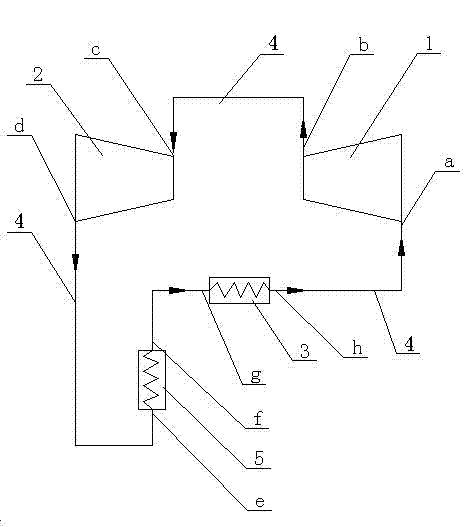
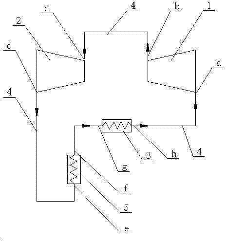
[0024] attached figure 1 Shown is a heat pump engine, which consists of a heat absorber (evaporator) 3, a compressor 1, a working machine 2, a radiator (condenser) 5, a pipeline 4 and a circuit formed by connecting them and a circuit working in the circuit. Composition of working fluid: the outlet h of the heat absorber 3 is connected with the inlet a of the compressor 1 through a pipeline, and the outlet b of the compressor 1 is connected with the inlet c of the working machine 2 through a pipeline. The outlet d of the working machine 2 is connected with the inlet e of the radiator 5 through a pipeline, and the outlet f of the radiator 5 is connected with the inlet g of the heat absorber 3 through a pipeline. When the system starts to operate, the compressor 1 is first started, and at this time, the working fluid in the heat absorbe...


PUM


Abstract

The invention relates to a heat engine system, in particular to a heat pump type engine. According to a heat pump circulation principle and a double-circulation afterheat recycling principle, a heat absorber absorbs heat energy in the nature, the absorbed heat energy and heat energy converted from mechanical energy of a compressor are integrally inputted into an acting machine via the compressor, and the acting machine outputs mechanical power outwards. The heat pump type engine consists of the heat absorber, the compressor, the acting machine, a radiator, pipelines and working media working in the pipelines; and by the aid of the pipelines, a flow outlet of the heat absorber is communicated with a flow inlet of the compressor, a flow outlet of the compressor is communicated with a flow inlet of the acting machine, a flow outlet of the acting machine is communicated with a flow inlet of the radiator, and a flow outlet of the radiator is communicated with a flow inlet of the heat absorber. Low-level heat energy is converted into high-level heat energy, and then is converted into the mechanical energy to be outputted, and energy utilization rate can be improved effectively.

Description

technical field [0001] The present invention relates to a thermal engine system, especially utilizing a heat absorber to absorb heat energy in nature, and inputting the heat energy absorbed by the heat absorber and the heat energy converted from the mechanical energy of the compressor itself into a work machine through a compressor, and the work machine outputs mechanical energy to the outside. Powerful thermodynamic cycle system. Background technique [0002] People know that there is a heat pump cycle system, which is mainly composed of evaporator (heat absorber), compressor, condenser (radiator), throttle valve (expansion valve), pipeline and working fluid in it. The evaporator can be used to absorb heat energy in nature, and the heat energy absorbed by the evaporator and the heat energy transformed by the compressor's own mechanical energy can be input into the condenser through the compressor, and the condenser can discharge heat to the required space; this circulation ...

Claims


Application Information

Patent Timeline
IPC IPC(8): F01K25/00
Inventor 王政玉王超颖张玉芹
Owner 王政玉
Why Eureka
Try Eureka