
Hydraulic jet pump capable of realizing reverse-circulating production and reverse-circulating lifting of pump core

A hydraulic injection and reverse circulation technology, applied in jet pumps, pumps, non-displacement pumps, etc., can solve the problems of site management and operation troubles, complex downhole string structure, increased workload, etc., and achieve the effect of mechanical impurities deposition Good, reduce the risk of overhaul and scrapping, and the effect of easy operation

Inactive Publication Date: 2012-07-11
TIANJIN LONGXIN PETROLEUM MACHINERY MFG CO LTD
View PDF5 Cites 8 Cited by
  • Summary
  • Abstract
  • Description
  • Claims
  • Application Information

AI Technical Summary

Problems solved by technology

Such problems include (1) the complex structure of the downhole tubing string, which increases the workload of the operation, increases the operating cost, and increases the production cost; Small casing and casing-changing wells are not suitable, so the adaptability is narrow; (3) During positive and negative circulation production, it is necessary to change the direction of the power fluid on the outer runner working cylinder, which brings troubles to site management and operation

Method used


Image

  • Hydraulic jet pump capable of realizing reverse-circulating production and reverse-circulating lifting of pump core
  • Hydraulic jet pump capable of realizing reverse-circulating production and reverse-circulating lifting of pump core
  • Hydraulic jet pump capable of realizing reverse-circulating production and reverse-circulating lifting of pump core

Examples


Embodiment Construction

[0020] The present invention will be described in further detail below through specific examples. The following examples are only descriptive and not restrictive, and cannot limit the protection scope of the present invention.

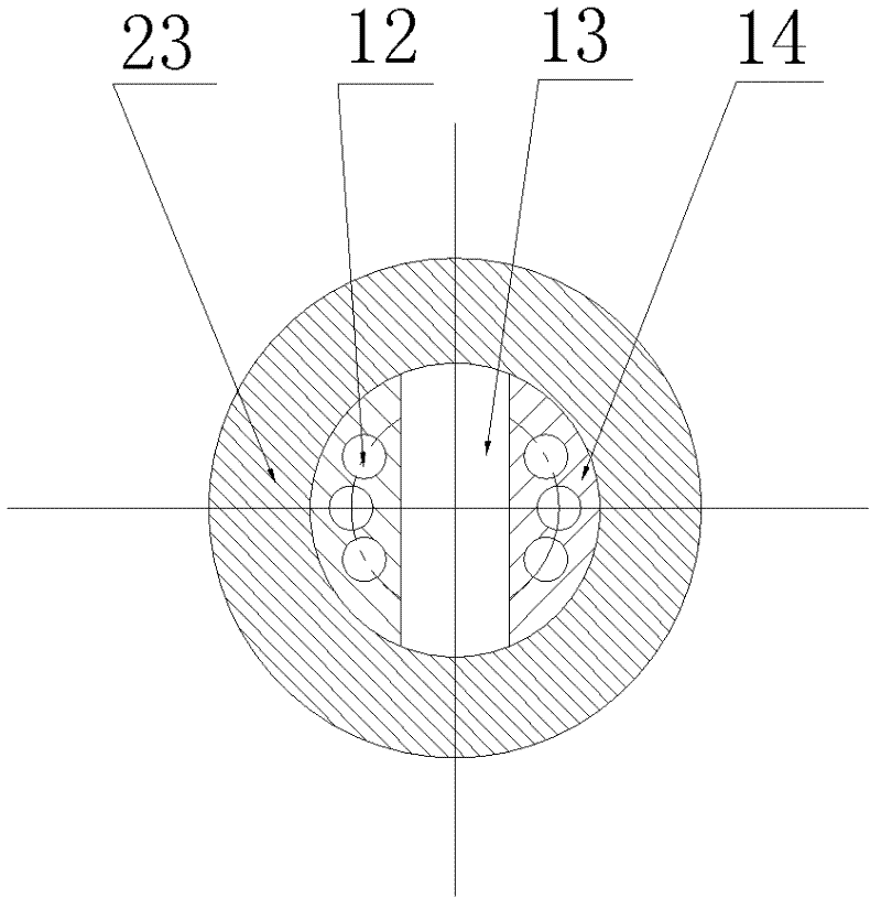
[0021] A reverse circulation production, reverse circulation pump core hydraulic jet pump, consisting of a working cylinder and a pump core. The working cylinder includes an upper joint 20, an upper sealing sub-section 22, a main cylinder body 23 and a lower joint 26, and the upper sealing sub-section An upper high-pressure sealing ring sealing surface 21 is made on the inner wall, a lower high-pressure sealing ring sealing surface 25 is made on the lower part of the main cylinder, and a working cylinder liquid inlet 11 is made on the upper part of the main cylinder. The pump core includes an overshot body 1 connected in sequence. , Pump rubber cylinder 2, upper connection sub 3, pump cylinder 10, high and low pressure dividing sub section 14, lower connec...


PUM


Abstract

The invention relates to a hydraulic jet pump capable of realizing reverse-circulating production and reverse-circulating lifting of a pump core, which comprises a working cylinder and the pump core. The working cylinder comprises an upper joint, an upper sealing nipple, a main cylinder body and a lower joint. The pump core comprises a fishing head, a rubber lifting barrel, an upper connecting nipple, a pump barrel, a high-pressure and low-pressure dividing nipple, a lower connecting nipple and a pump inlet sieve pipe which are connected sequentially, a jet device is arranged in the pump barrel, an upper high-pressure sealing ring is assembled on the outer wall of the upper end of the upper connecting nipple, and a lower high-pressure sealing ring is assembled on the outer wall of the lower end of the high-pressure and low-pressure dividing nipple. The hydraulic jet pump is characterized in that an annular flow passage is formed among the upper sealing nipple, the upper connecting nipple which is arranged on the inner wall of the main cylinder body and corresponds to the pump core and the outer wall of the pump barrel, a sealing face of the upper high-pressure sealing ring is formed on the inner wall of the upper sealing nipple, a guide rail part is mounted between the high-pressure and low-pressure dividing nipple and the lower connecting nipple, and limit blocks which are embedded in rails of the guide rail part are symmetrically fixedly mounted on the main cylinder body.

Description

Technical field [0001] The invention relates to the technical field of oil extraction equipment, in particular to a reverse circulation production and reverse circulation pump core hydraulic jet pump. Background technique [0002] At present, with the continuous development of oil fields and the increase in the number of highly inclined and horizontal wells, conventional rod-based oil production techniques are no longer suitable. To meet the needs of development and production, only rodless oil extraction technology can be used, such as electric submersible pumps, submersible screw pumps, hydraulic jet pumps, and hydraulic piston pumps. However, due to the short operation cycle of submersible screw pump inspections and frequent pump cores of hydraulic piston pumps, these two types of pumps are rarely used. Most oilfields with steep and horizontal wells are produced by submersible electric pumps or hydraulic jet pumps. However, due to the decrease of formation energy, formation o...

Claims


Application Information

Patent Timeline
Patent Type & Authority Applications(China)
IPC IPC(8): F04F5/10F04F5/44E21B43/00
Inventor 刘树高张仁杰曹晖覃莉张兵
Owner TIANJIN LONGXIN PETROLEUM MACHINERY MFG CO LTD
Learn More