Balanced valve, hydraulic cylinder expansion control loop and crane

A balance valve and pilot control technology, applied in the field of balance valves, can solve problems such as frequent jitter, unstable work, frequent changes, etc.

Active Publication Date: 2012-07-11
ZOOMLION HEAVY IND CO LTD
View PDF7 Cites 24 Cited by
  • Summary
  • Abstract
  • Description
  • Claims
  • Application Information

AI Technical Summary

Problems solved by technology

Due to structural design reasons, this prior art balance valve has some insurmountable problems. For example, because D is determined by the flow capacity of the balance valve, this needs to be related to the working speed of the hydraulic working mechanism and the flow demand of the hydraulic actuator. and other factors, the hydraulic working mechanism selects a balance valve with matching flow capacity according to the application needs, so the size of D is relatively determined, and d belongs to the part of the control oil circuit, and it cannot be formed larger, otherwise it will lead to control oil flow. Insufficient quantity, difficult control and other defects, so the control ratio of the balance valve in the prior art is relatively large
In this case, although the balance valve can realize the function of descending speed limit in the process of descending speed limit, it is too sensitive to the change of load pressure. Once the load pressure changes slightly, the matching control oil pressure is required to change exponentially. Otherwise, the opening of the balance valve will change significantly, and during the working process of the hydraulic working mechanism, the load pressure often changes due to various reasons (especially in the hydraulic working mechanism using multi-stage telescopic cylinders), even if the load pressure Only slightly fluctuating, the opening of the balance valve will also change frequently, so that the balance valve in the prio...

Method used


Image

  • Balanced valve, hydraulic cylinder expansion control loop and crane
  • Balanced valve, hydraulic cylinder expansion control loop and crane
  • Balanced valve, hydraulic cylinder expansion control loop and crane

Examples


Embodiment Construction

[0060] The specific embodiments of the present invention will be described in detail below in conjunction with the accompanying drawings. It should be understood that the specific embodiments described here are only used to illustrate and explain the present invention, and the protection scope of the present invention is not limited to the following specific embodiments. .

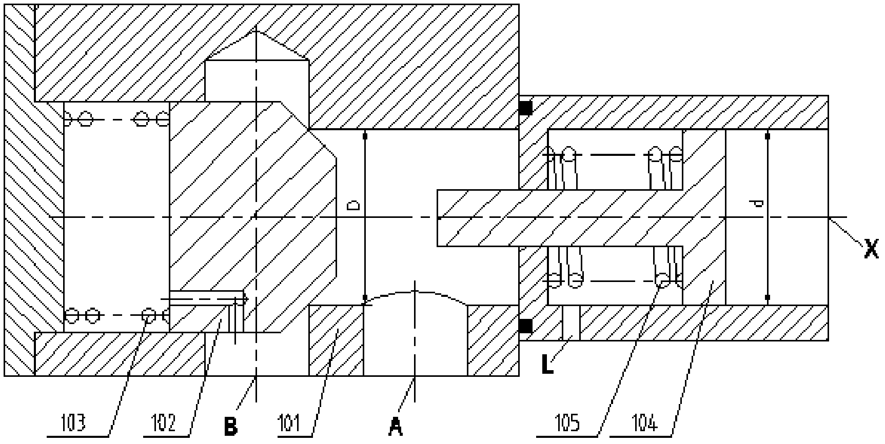
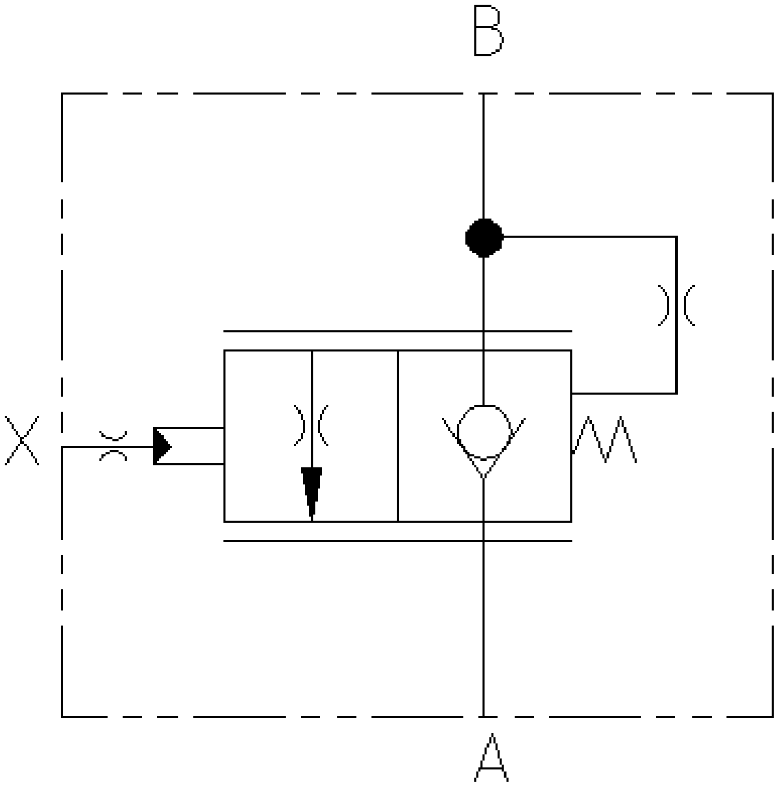
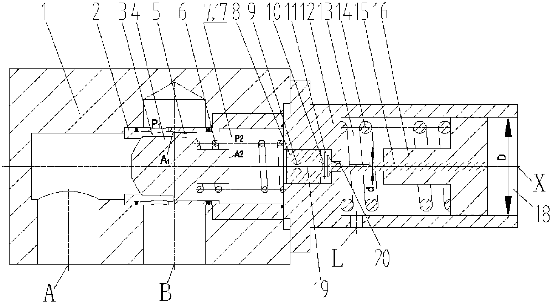
[0061] First of all, it needs to be explained that the balance valve of the present invention is a hydraulic component, and its core technical concept lies in its hydraulic control relationship, not in the specific valve structure. image 3 , Figure 4 as well as Image 6 with Figure 7 The specific valve structures shown are only specific structural forms to help those skilled in the art to understand, but the protection scope of the present invention should not be limited to these specific structural forms, for example, Figure 5 As far as the hydraulic control relationship of the preferred form of th...


PUM


Abstract

The invention provides balanced valve which comprises a main valve body (1) and a main valve core (4), wherein the main valve body (1) is provided with a positive oil outlet (A) and a reverse oil outlet (B); the main valve core (4) comprises a first acting surface (A1) and a second acting surface (A2) which are opposite to each other; the first acting surface is exposed in a first acting cavity (3) communicated with the reverse oil outlet; the second acting surface is exposed in a second acting cavity (17) communicated with the reverse oil outlet through a dumping groove (5); and the balanced valve further comprises a guiding control module which enables the second acting cavity to be selectively communicated with an oil draining port through a guiding control oil port (X). In addition, the invention also provides a hydraulic cylinder expansion control loop and a hydraulic crane. Due to the guiding control method, a large control ratio can be obtained through controlling the size of a guiding piston rod, the descending speed limitation control of the balanced valve is more sensitive, the influence of the load pressure on the openness of the main valve core is slight, frequent shaking can not be generated, the work stability is good, and the energy-saving effect is excellent.

Description

technical field [0001] The present invention relates to a balance valve, in particular to a balance valve. On this basis, the present invention also relates to a hydraulic cylinder expansion and contraction control circuit provided with the balance valve. Furthermore, the invention also relates to a crane. Background technique [0002] The balance valve is a valve widely used in construction machinery equipment, which plays an important role in improving the working performance of some hydraulic working mechanisms of construction machinery, such as the lifting mechanism, luffing mechanism and telescopic mechanism of hydraulic cranes. Typically, these working mechanisms use hydraulic cylinders as hydraulic actuators, and the hydraulic cylinders need to be telescopically controlled through the hydraulic cylinder telescopic control circuit, and the balance valve is generally set on the working oil circuit connected to the rodless chamber of the hydraulic cylinder. [0003] Wh...

Claims


Application Information

Patent Timeline
IPC IPC(8): F15B13/02
Inventor 左春庚陶军张劲谢海波宋建清
Owner ZOOMLION HEAVY IND CO LTD
Why Eureka
Try Eureka