Evaporating plant in refrigerating system

An evaporating device and refrigeration system technology, applied in the field of refrigeration systems and evaporating devices, can solve the problems of reducing the heat transfer efficiency outside the tube, easy fouling after long-term use, and thin baffle structure, so as to increase the degree of automation and reduce the evaporator. Risk, effect in favor of deposition and discharge

Active Publication Date: 2013-10-16
TAIZHOU LONGJIANG CHEM MACHINERY TECH
View PDF9 Cites 0 Cited by
  • Summary
  • Abstract
  • Description
  • Claims
  • Application Information

AI Technical Summary

Problems solved by technology

The device adjusts the liquid supply pipe so that the port is higher than the bottom of the separator. Although the stirring of the lubricating oil when the ammonia liquid enters the heat exchanger is reduced, the disturbance of the lubricating oil when the ammonia liquid enters the heat exchanger makes the lubrication There is still a risk of oil entering the heat exchanger; in addition, the structure of the baffle at the inlet of the refrigerant is thin, and it is easy to cause the baffle to fall off under the action of corrosion and erosion; It is easy to accumulate fouling during long-term use, which further reduces the heat transfer efficiency outside the tube

Method used


Image

  • Evaporating plant in refrigerating system
  • Evaporating plant in refrigerating system
  • Evaporating plant in refrigerating system

Examples


Embodiment 1

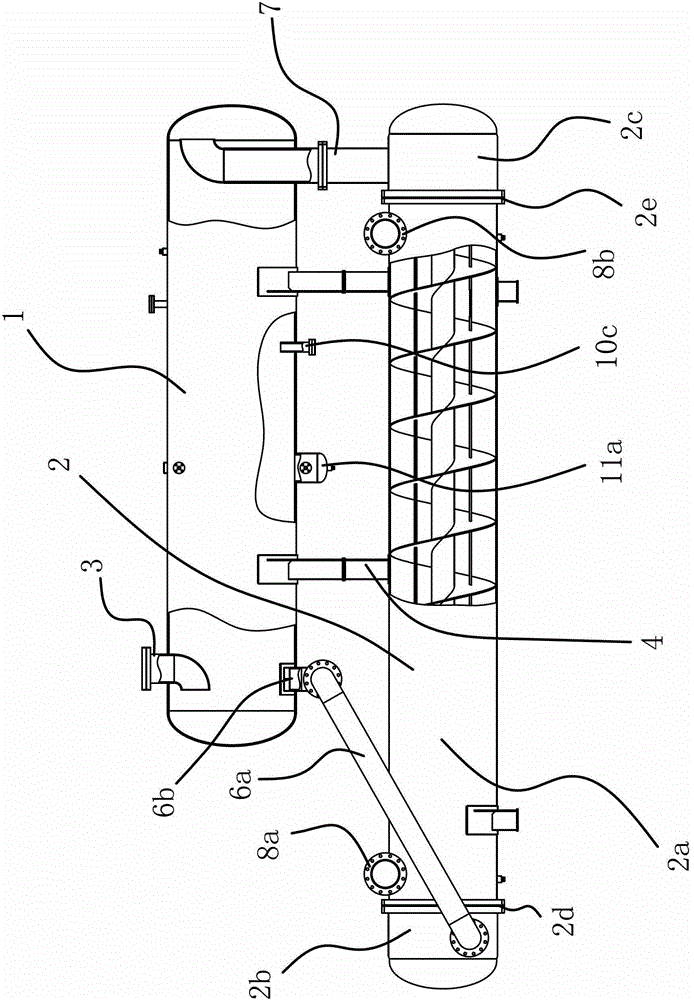
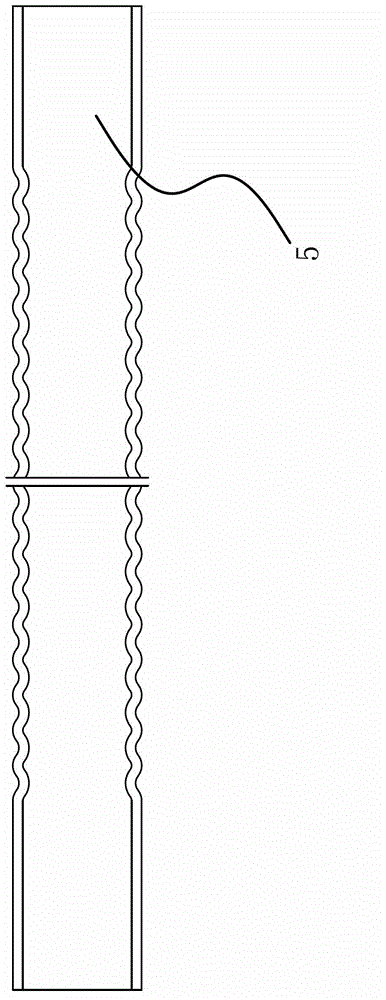
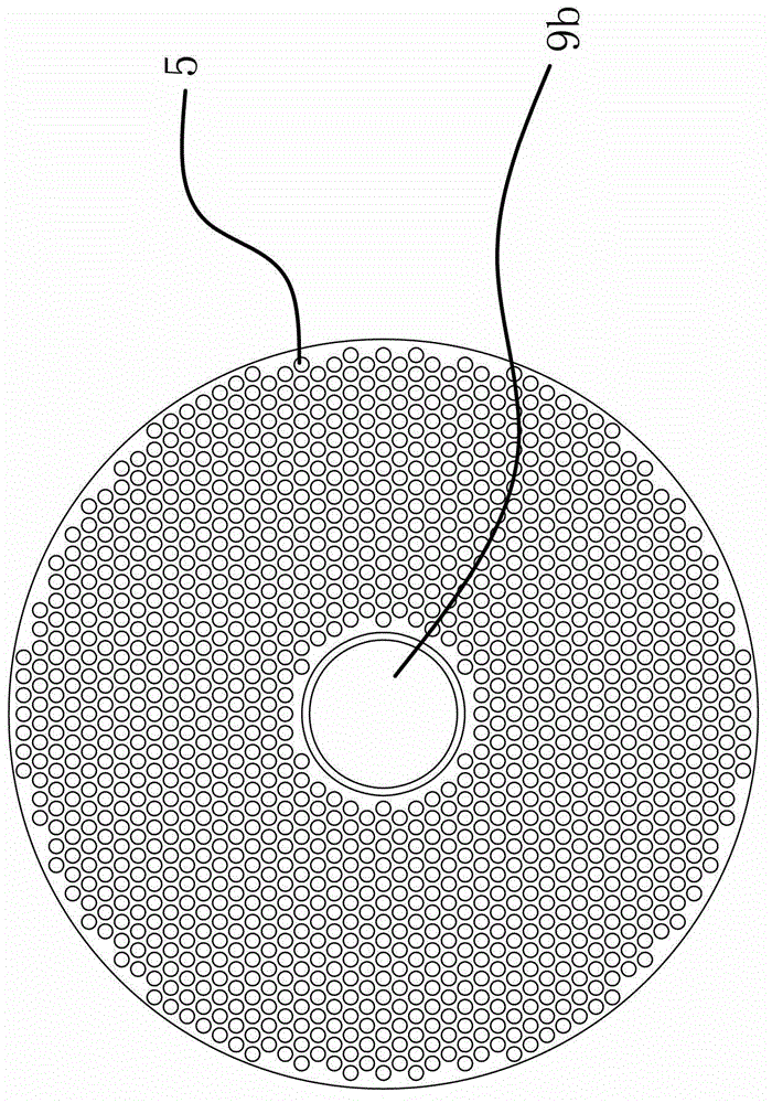
[0035] like Figures 1 to 7 shown, an evaporation device in a refrigeration system, such as figure 1 As shown, it includes a separator 1 and an evaporator 2 with a return pipe 3, and the refrigeration system also includes a compressor and a condenser. The compressor is connected with the return pipe 3, and the separator 1 is located above the evaporator 2. Seat 4 is fixed. The cooling medium used in this refrigeration system is ammonia liquid, and the cooling medium is brine. There are several heat exchange tubes 5 in the evaporator 2, such as figure 2 , image 3 As shown, the heat exchange tube 5 is a corrugated tube. The uneven inner surface increases the disturbance of the cooling medium in the heat exchange tube 5, and increases the heat transfer coefficient of the cooling medium in the heat exchange tube 5; at the same time, the corrugated tube or the cross-corrugated tube increases the wall of the heat exchange tube 5. The surface area increases the efficiency of h...

Embodiment 2

[0045] The content in the second embodiment is roughly the same as that in the first embodiment, except that the heat exchange tube 5 in the first embodiment is a corrugated tube; Figure 8 As shown, the heat exchange tube 5 in the second embodiment is a cross-ribbed tube.


PUM


Abstract

The invention provides an evaporating plant in a refrigerating system, which belongs to the technical field of refrigeration. The evaporating plant solves technical problems that lubricating oil can possibly flow into a heat exchanger of an existing evaporating plant in a refrigerating system and the like. The evaporating plant in the refrigerating system comprises a separator and an evaporator, the separator is provided with a steam return pipe and positioned above the evaporator, a plurality of heat exchange pipes are arranged in the evaporator, one end of each heat exchange pipe is communicated with the separator via a downcomer, the other end of each heat exchange pipe is communicated with a steam raising pipe, the other end of the steam raising pipe is a steam outlet end communicated with the separator, the separator is further connected with a liquid level control mechanism, when the liquid level of cooling media in the separator is lower than a first set value, liquid can be automatically supplemented to the separator by the aid of the liquid level control mechanism, and when the liquid level of the cooling working media in the separator is higher than a second set value, liquid supplementing to the separator can be automatically stopped by the aid of the liquid level control mechanism. The evaporating plant in the refrigerating system has the advantages that risks that lubricating oil enters the evaporator are reduced, and the lubricating oil deposits and is drained advantageously.

Description

technical field [0001] The invention belongs to the technical field of refrigeration, and relates to a refrigeration system, in particular to an evaporation device in the refrigeration system. Background technique [0002] Before artificial refrigeration began to develop, people had used natural ice and snow to maintain low temperature conditions in simple equipment. However, with the development of society, the requirements for refrigeration are getting higher and higher, and the simple use of ice and snow is far from meeting people's requirements. Therefore, modern refrigeration systems have emerged as the times require. The cooling methods of refrigeration systems include direct cooling and indirect cooling. 1. Indirect cooling is generally used in medium-sized refrigeration systems. This method has good cooling effect and constant temperature, so it is widely used in chemical, pharmaceutical, and food industries. [0003] The refrigeration system mainly includes a compr...

Claims


Application Information

Patent Timeline
Patent Type & Authority Patents(China)
IPC IPC(8): F25B39/02F25B43/00F25B43/02F25B41/04F25B49/02
Inventor 林文贤熊从贵
Owner TAIZHOU LONGJIANG CHEM MACHINERY TECH
Why Eureka
Try Eureka