Device and method for aligning pinhole of point-diffraction interferometer

A point-diffraction interferometer and pinhole technology, applied in the direction of using optical devices, measuring devices, instruments, etc., can solve problems such as inapplicability, achieve the effect of improving alignment speed and overcoming misjudgment

Inactive Publication Date: 2012-07-11
CHANGCHUN INST OF OPTICS FINE MECHANICS & PHYSICS CHINESE ACAD OF SCI
View PDF3 Cites 24 Cited by
  • Summary
  • Abstract
  • Description
  • Claims
  • Application Information

AI Technical Summary

Problems solved by technology

[0007] Due to the different structures of the point diffraction interferometer when detecting the system wave aberration and the surface deviation of the detection element, the alignment technology of the point diffraction interferometer pinhole described in the

Method used


Image

  • Device and method for aligning pinhole of point-diffraction interferometer
  • Device and method for aligning pinhole of point-diffraction interferometer
  • Device and method for aligning pinhole of point-diffraction interferometer

Examples


Embodiment Construction

[0017] The device and application method of the present invention will be further described below in conjunction with the accompanying drawings.

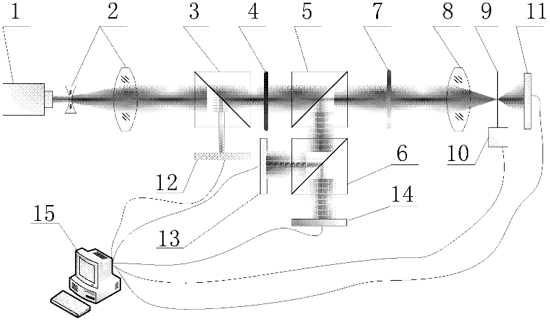
[0018] Such as figure 1 As shown, the present invention provides a device for the pinhole alignment of the point diffraction interferometer, through which the precise alignment and real-time monitoring of the focused light spot and the diffraction pinhole in the point diffraction interferometer can be realized. The device includes a laser 1, a laser beam expander 2, a first dichroic prism 3, a half-wave plate 4, a second dichroic prism 5, a third dichroic prism 6, a quarter-wave plate 7, a focusing mirror 8, A pinhole plate 9 , a three-dimensional scanning micro-adjustment mechanism 10 , a first laser power meter 11 , a second laser power meter 12 , a third laser power meter 13 , a position detector 14 and a computer 15 . Wherein the laser light emitted by the laser device 1 is linearly polarized light; the laser beam expander 2 ca...


PUM


Abstract

The invention discloses a device and a method for aligning a pinhole of a point-diffraction interferometer, belonging to the technical field of optical precise debugging, namely a device and a method for aligning the pinhole of the point-diffraction interferometer provided to realize real-time monitoring of precise aligning and aligning states of a focusing spot and a diffraction pinhole in the point-diffraction interferometer. The device comprises a laser device, a laser beam expander, a first dispersion prism, a half-wave plate, a second dispersion prism, a third dispersion prism, a quarter-wave plate, a focus lens, a pinhole plate, a three-dimensional scanning and micro-adjusting mechanism, a first laser power meter, a second laser powder meter, a third laser power meter, a position detector and a computer. According to the device and the method disclosed by the invention, the aligning speed is increased; the pinhole aligning state is quickly aligned again when being monitored; power change of the laser device is detected by a sole laser power meter in the invention and the aligning state is reflected by a ratio of the laser power instead of an absolute value so that error judgment on the aligning state of the pinhole caused by laser power change is overcome.

Description

technical field [0001] The invention belongs to the technical field of optical precision adjustment, and relates to a precision alignment device and method for pinholes in point diffraction interferometers. Background technique [0002] In order to achieve the required resolution and critical size of the projection lithography objective lens, the wave aberration of the optical system needs to reach the diffraction limit. The extreme ultraviolet lithography works in the extreme ultraviolet band with a wavelength of 13-14nm, which requires the wave aberration of the optical system It should be less than 1nmRMS, and the surface deviation of a single mirror surface should be 0.25nmRMS. To achieve such high-precision optical processing, high-precision optical detection technology must first be realized. Conventional interferometric detection technologies such as Fizeau interferometer and Tieman interferometer are limited by the accuracy of the reference surface, and it is difficu...

Claims


Application Information

Patent Timeline
IPC IPC(8): G01B9/02
Inventor 张海涛于杰马冬梅金春水
Owner CHANGCHUN INST OF OPTICS FINE MECHANICS & PHYSICS CHINESE ACAD OF SCI
Why Eureka
Try Eureka