Multi-rotor joint vibration mode balancing method for single support shafting steam turbine generator unit

A turbo-generator set, vibration-shape balancing technology, applied in the static/dynamic balance test, machine/structural component test, measuring device, etc., can solve problems such as large aggravation interval, impossibility of implementation, unstable power frequency vibration, etc. , to achieve the effect of improving balance efficiency and precision

Active Publication Date: 2012-07-11
ELECTRIC POWER RES INST OF STATE GRID ZHEJIANG ELECTRIC POWER COMAPNY
View PDF4 Cites 21 Cited by
  • Summary
  • Abstract
  • Description
  • Claims
  • Application Information

AI Technical Summary

Problems solved by technology

This type of steam turbine unit adopts a unique single-bearing support structure. The single support reduces three bearings, and the vibration monitoring of the rotor also reduces the measuring point information at three planes correspondingly. Only the vibration information of a single end of the rotor can be tested. There is no mutual phase relationship, and the first-order and second-order vibration shapes of the rotor cannot be judged from the mutual phase relationship of the rotor
When the vibration failure of the single-supported shafting ultra-supercritical unit occurs, the power frequency vibration is unstable. Regardless of the no-load constant speed or the load process, the power frequency vibration always fluctuates and changes drastically, and there is a strong coupling effect between the shaft vibrations. The on-site dynamic balance processing brings certain difficulties
[0003] For

Method used


Image

  • Multi-rotor joint vibration mode balancing method for single support shafting steam turbine generator unit
  • Multi-rotor joint vibration mode balancing method for single support shafting steam turbine generator unit
  • Multi-rotor joint vibration mode balancing method for single support shafting steam turbine generator unit

Examples


Embodiment Construction

[0020] The present invention is a multi-rotor joint mode balance method for a single-support shafting turbogenerator set, which will be described in detail below (the rated speed is 3000r / min as an example):

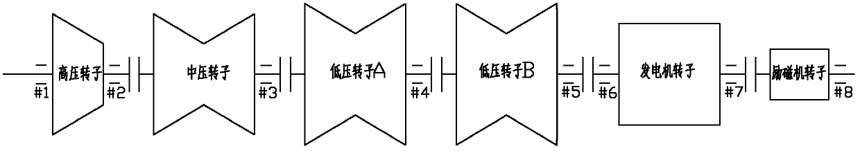
[0021] The shaft system of the steam turbine unit consists of a high-pressure rotor, a medium-pressure rotor, two low-pressure rotors, a generator rotor and an exciter rotor. The rotors are connected by rigid couplings. The high-pressure rotor is double-supported, and the medium-pressure rotor and two The low-pressure rotors are all single-supported, and No. 1-5 bearings are arranged between the above-mentioned four rotors. The rotor of the generator and the exciter is a three-supported structure, and the shafting arrangement is as follows: figure 1 shown.

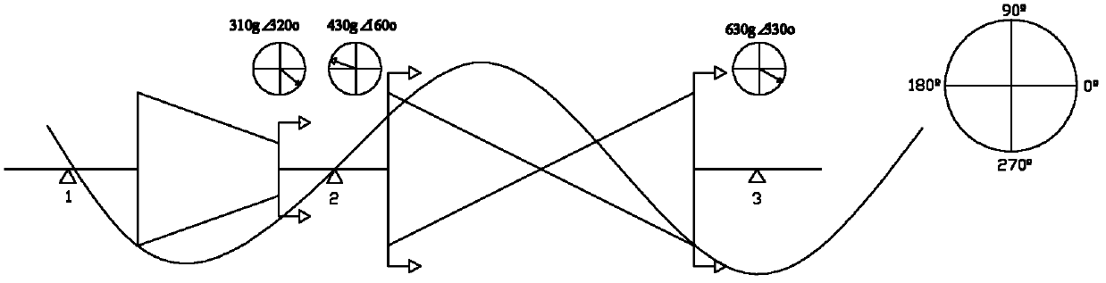
[0022] (1) Rotor vibration vector calculation

[0023] When the steam turbine unit is running at a rated speed of 3000r / min, according to the vibration test system, the power frequency shaft vibration vector A of ea...


PUM


Abstract

The invention discloses a multi-motor joint vibration mode balancing method for a single support shafting steam turbine generator unit. At present, during on-site dynamic balancing of a single support shafting supercritical steam turbine generator unit, vibration information of two ends of rotors is not provided and shaft vibrations influence each other by coupling, so that a certain difficulty is brought into the on-site dynamic balancing of a shafting. According to the multi-rotor joint vibration mode balancing method, unbalanced types of the shafting are judged and calculated by calculating vibration vectors and vibration mode harmonic components and combining characteristics of a single supporting shafting structure according to shaft vibration magnitude values and shaft vibration phases of each rotor of the shafting at a critical rotating speed and a working rotating speed, and then a joint vibration mode of multiple rotors is identified; and a weight-increasing scheme of each plane is directly obtained according to a lag angle, mass-basis response coefficients and a first-time weight-increasing interval, and a group of increased weights are added to a related plane once. By the multi-motor joint vibration mode balancing method, the balancing efficiency and the accuracy of the single support shafting rotors are significantly increased.

Description

technical field [0001] The invention relates to the field of fault diagnosis and vibration treatment of an ultra-supercritical turbo-generator set, in particular to a multi-rotor combined vibration-shape balancing method for a single-supported shaft system ultra-supercritical turbo-generator set. Background technique [0002] SAIC-Siemens ultra-supercritical turbogenerator unit is becoming the most competitive coal-fired unit in my country in the early 21st century due to its technical advantages of high efficiency, energy saving and environmental protection. The market application prospect is very good. By the end of 2010, it has More than 30 units of 1000MW and 660MW were put into operation. This type of steam turbine unit adopts a unique single-bearing support structure. The single support reduces three bearings, and the vibration monitoring of the rotor also reduces the measuring point information at three planes correspondingly. Only the vibration information of a single...

Claims


Application Information

Patent Timeline
IPC IPC(8): G01M1/38
Inventor 应光耀童小忠吴文健马思聪
Owner ELECTRIC POWER RES INST OF STATE GRID ZHEJIANG ELECTRIC POWER COMAPNY
Why Eureka
Try Eureka