Radio frequency coil for guiding ultrasonic focusing system and design method thereof

A radio frequency coil, ultrasonic focusing technology, applied in ultrasonic therapy, application, magnetic resonance measurement and other directions, can solve the problems of optimization or compensation technology that has not been reported, and the inability of ultrasonic energy focusing equipment to provide treatment space, etc.

Inactive Publication Date: 2012-07-11
SOUTHERN MEDICAL UNIVERSITY
View PDF5 Cites 6 Cited by
  • Summary
  • Abstract
  • Description
  • Claims
  • Application Information

AI Technical Summary

Problems solved by technology

Due to the high complexity of the numerical calculation of the inverse method itself, in the previous inverse method design of RF coils, the coil support shell was usually assumed to be cylindrical or conical to facilitate modeling and reduce computational complexity. However, Such an ordinary cylindrical or conical support shell will cause the calculated current density to be distributed on the entire surface of the shell, which cannot prov

Method used


Image

  • Radio frequency coil for guiding ultrasonic focusing system and design method thereof
  • Radio frequency coil for guiding ultrasonic focusing system and design method thereof
  • Radio frequency coil for guiding ultrasonic focusing system and design method thereof

Examples


Embodiment 1

[0051] Design the radio frequency coil according to a design method for guiding the radio frequency coil of the ultrasonic focusing system provided by the present invention, the process is as follows:

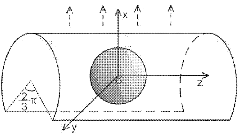
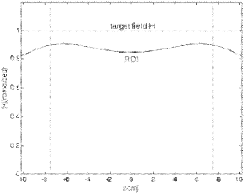
[0052] (1) Propose a target magnetic field according to the specific magnetic field distribution requirements: According to the reciprocity principle, the performance of the radio frequency receiving coil is related to the uniformity of the magnetic field generated when the coil structure is used as the transmitting mode, so the target tissue surface is set The magnetic field is uniform, in order to simplify the calculation, its size is set as the unit field strength of 1 Henry; the supporting shell of the coil used is set to be cylindrical; since the current density is distributed on the surface of the cylinder, only consider in the theoretical modeling The current density components in the direction of the rotation angle and the length axis of the cylinder, and each current de...

Embodiment 2

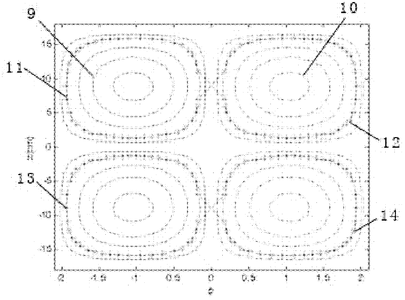
[0066] The three-dimensional structure of the radio frequency coil designed according to the method of embodiment 1 is as Figure 5 As shown, it includes a supporting shell made of non-magnetic plexiglass material, and the coils arranged on the surface of the supporting shell are made of copper strip material with a width of 15mm. The coil loop includes two sets of 8-shaped loops (2, 3) and a circular compensating loop 4. Two sets of figure-of-eight loops follow figure 2 The center star lines (11, 12, 13, 14) are arranged, and the annular compensating circuit 4 is arranged in the middle of two groups of 8-shaped circuits, that is, on the central ring line of the cylinder. The annular compensation circuit divides the arc gap at the bottom of the radio frequency coil into two parts, the left and the right. In clinical thermal ablation operations, the ultrasonic energy-focusing device can be placed in one of the parts as needed. There are insulating pads 8 at the crossing part...

Embodiment 3

[0069] Adopt the radio frequency coil designed in embodiment 2 to carry out the water model test of low-field magnetic resonance, the obtained image is as follows Figure 6 shown. Among them, the imaging equipment used is a 0.4T permanent magnet open magnetic resonance imaging system, model specification: OPER-0.4; product standard number: YZB / country 0228-2008. The following specific parameters are used:

[0070]

[0071] From Figure 6 It can be seen from the figure that the radio frequency coil structure designed based on the method of the present invention is applied in a low-field magnetic resonance system, and the scanned image of the water model has uniform brightness, indicating that the method provided by the present invention can be used to design the radio frequency coil. Complete the imaging function well.

[0072] Adopt the radio frequency coil designed in embodiment 2 to carry out the human body image scanning test of low-field magnetic resonance, the obtai...


PUM

PropertyMeasurementUnit
Widthaaaaaaaaaa
Radiusaaaaaaaaaa
Lengthaaaaaaaaaa

Abstract

The invention provides a radio frequency coil for guiding an ultrasonic focusing system and a design method thereof, and belongs to the technical field of magnetic resonance imaging. A coil support housing used by the radio frequency coil is of a cylindrical surface; furthermore, the cylindrical surface is radially provided with an arc-surface gap alpha; a coil loop is arranged on the support housing and comprises two groups of 8-shaped loops and a group of annular compensation loop; the two groups of the 8-shaped loops are arranged in parallel along the axial direction of a cylinder, and two rings in the same 8-shaped loop are arranged along the circumferential direction of the cylinder; the annular compensation loop is arranged in the middle of the two groups of the 8-shaped loops; insulating pads are arranged at the intersected parts of the 8-shaped loops; the two groups of the 8-shaped loops are connected in parallel to form a channel; and the annular compensation coil constitutes the channel alone and is connected with an output circuit board for sending out signals. The radio frequency coil device can enable a low-field magnetic resonance device to be matched with the ultrasonic focusing system for use, provide a sufficient surgical operation space for a doctor and realize real-time non-invasive monitoring of temperature of tissues of a human body during a thermal ablation operation.

Description

technical field [0001] The invention relates to a magnetic resonance imaging technology, in particular to a radio frequency coil structure for accurate measurement of thermal ablation parameters in ultrasonic focused thermal ablation. Background technique [0002] Focused ultrasonic ablation (FUS) has attracted much attention in clinical treatment, especially in tumor treatment, because of its good orientation, non-invasiveness and safety. Its mechanism is to use the tissue penetrating and focusable characteristics of ultrasound to accurately focus the countless beams of low-energy ultrasound emitted by the ultrasound transducer on the target tissue in the body, and to cause coagulation necrosis of the tissue in the focused area instantaneously through the thermal effect of ultrasound on the tissue. Therefore, the therapeutic effect of thermal ablation surgery is closely related to the temperature of the target tissue. During the treatment process, it is necessary to monitor...

Claims


Application Information

Patent Timeline
IPC IPC(8): G01R33/34A61B5/055A61B5/01A61N7/02
Inventor 辛学刚韩继钧陈武凡
Owner SOUTHERN MEDICAL UNIVERSITY
Why Eureka
Try Eureka