Supercharge Your Innovation With Domain-Expert AI Agents!

Delay lock loop circuit

A delay-locked loop and circuit technology, applied in the direction of automatic control of electrical components and power, can solve the problem that the delay-locked loop circuit cannot be adjusted automatically, and achieve the effect of reducing the difficulty of design and avoiding trouble.

Active Publication Date: 2012-07-11
SHANGHAI BEILING
View PDF3 Cites 2 Cited by
  • Summary
  • Abstract
  • Description
  • Claims
  • Application Information

AI Technical Summary

Problems solved by technology

[0008] The present invention provides a delay-locked loop circuit for the above-mentioned problems in the prior art, to solve the problem that the delay-locked loop circuit in the prior art cannot be automatically adjusted when it works incorrectly, and can only be activated by giving a reset signal from the upper layer system. Problems with the circuit working properly

Method used


Image

  • Delay lock loop circuit
  • Delay lock loop circuit
  • Delay lock loop circuit

Examples


Embodiment Construction

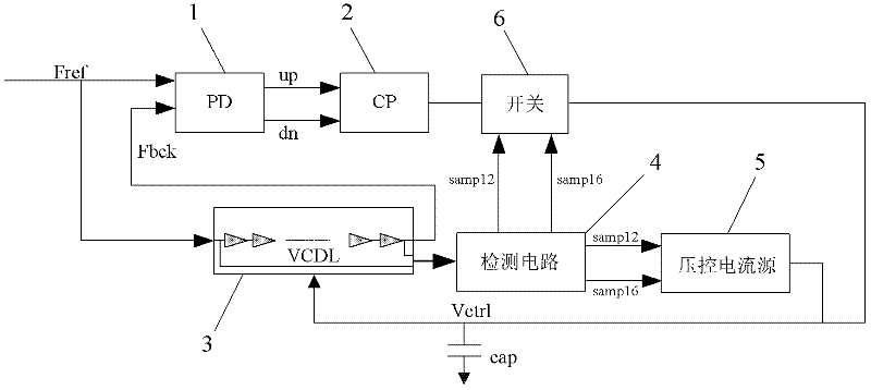
[0023] Specific embodiments of the present invention will be described in detail below in conjunction with the accompanying drawings.

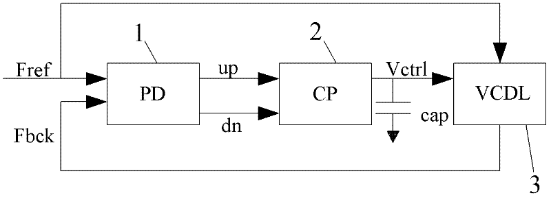
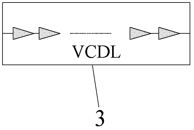
[0024] like image 3 As shown, the delay locked loop circuit of the present invention includes a phase comparator (PD) 1 for comparing the phase relationship between the input clock signal Fref and the feedback signal Fbck to generate a leading signal up and a lagging signal dn. and a charge pump (CP) 2 controlled by the hysteresis signal dn, a filter capacitor cap connected to the output terminal of the charge pump 2 and used to provide the DC voltage signal, and a filter capacitor cap used to respond to the DC voltage signal to process the input clock signal Fref In addition to delaying the voltage-controlled delay chain (VCDL) 3 that generates the feedback signal Fbck, it also includes a detection circuit 4, a voltage-controlled current source 5 and a switch 6, wherein,

[0025] The detection circuit 4 is configured to judge the magnitude ...


PUM


Abstract

The invention discloses a delay lock loop circuit. The delay lock loop circuit comprises a phase comparator, a charge pump, a voltage-controlled delay link and a filter capacitor, and further comprises a detection circuit, a voltage-controlled current source and a switch, wherein the detection circuit is configured to judge the size relationship between the delay time of the voltage-controlled delay link and the clock cycle of an input clock signal, and output a control signal for controlling the voltage-controlled current source and the switch; the voltage-controlled current source is configured to receive the control signal and regulate the magnitude of the output current according to the control signal; and the switch is positioned on the output line of the charge pump and configured to receive the control signal and switch on and off according to the control signal. The delay lock loop circuit added with the detection circuit can automatically detect the working state of the voltage-controlled delay link and regulate the delay time, and can be reset without an additional upper system.

Description

technical field [0001] The invention relates to a delay locked loop (DLL) circuit, in particular to a delay locked loop circuit capable of self-adjustment. Background technique [0002] like figure 1 As shown, the delay locked loop (DLL) circuit in the prior art includes a phase relationship for comparing the input clock signal Fref and the feedback signal Fbck to generate the lead signal up (the feedback signal leads the input clock signal) and the lag signal dn (the feedback signal A phase comparator (PD) 1 lagging the input clock signal), a charge pump (CP) 2 controlled by the leading signal up and a lagging signal dn, a filter capacitor cap connected to the output of the charge pump 2 and providing a DC voltage signal and a voltage-controlled delay chain (VCDL) 3 for generating said feedback signal Fbck by delaying said input clock signal Fref in response to a DC voltage signal. [0003] like figure 2 As shown, a voltage-controlled delay chain (VCDL) 3 includes multi...

Claims


Application Information

Patent Timeline
Patent Type & Authority Applications(China)
IPC IPC(8): H03L7/08
Inventor 郑佳鹏
Owner SHANGHAI BEILING
Features
  • R&D
  • Intellectual Property
  • Life Sciences
  • Materials
  • Tech Scout
  • Unparalleled Data Quality
  • Higher Quality Content
  • 60% Fewer Hallucinations
Learn More