
Hydraulic drive device of hydraulic operating machine

一种液压工程机械、驱动装置的技术,应用在传动装置控制、液体变容式机械、机械设备等方向,能够解决过滤器的网眼易堵住等问题

Active Publication Date: 2012-07-11
HITACHI CONSTRUCTION MACHINERY CO LTD
View PDF6 Cites 4 Cited by
  • Summary
  • Abstract
  • Description
  • Claims
  • Application Information

AI Technical Summary

Problems solved by technology

Along with this, it becomes difficult to generate combustion of particulate matter by the heat of the exhaust gas, and the meshes of the filter of the exhaust gas purification device are easily clogged.

Method used


Image

  • Hydraulic drive device of hydraulic operating machine
  • Hydraulic drive device of hydraulic operating machine
  • Hydraulic drive device of hydraulic operating machine

Examples


no. 1 approach

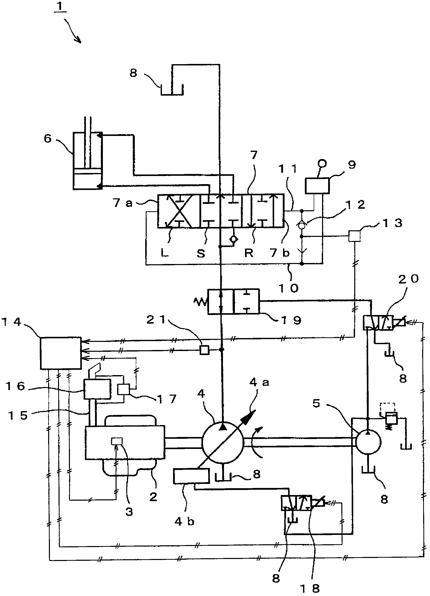
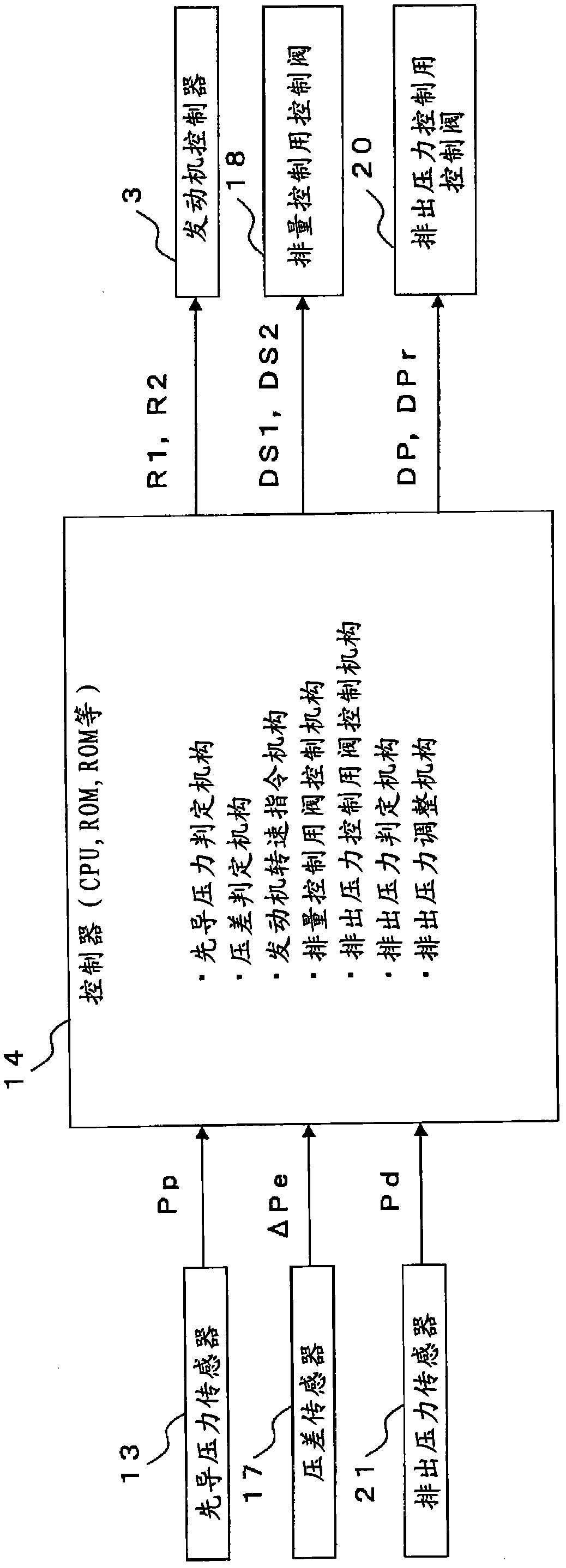
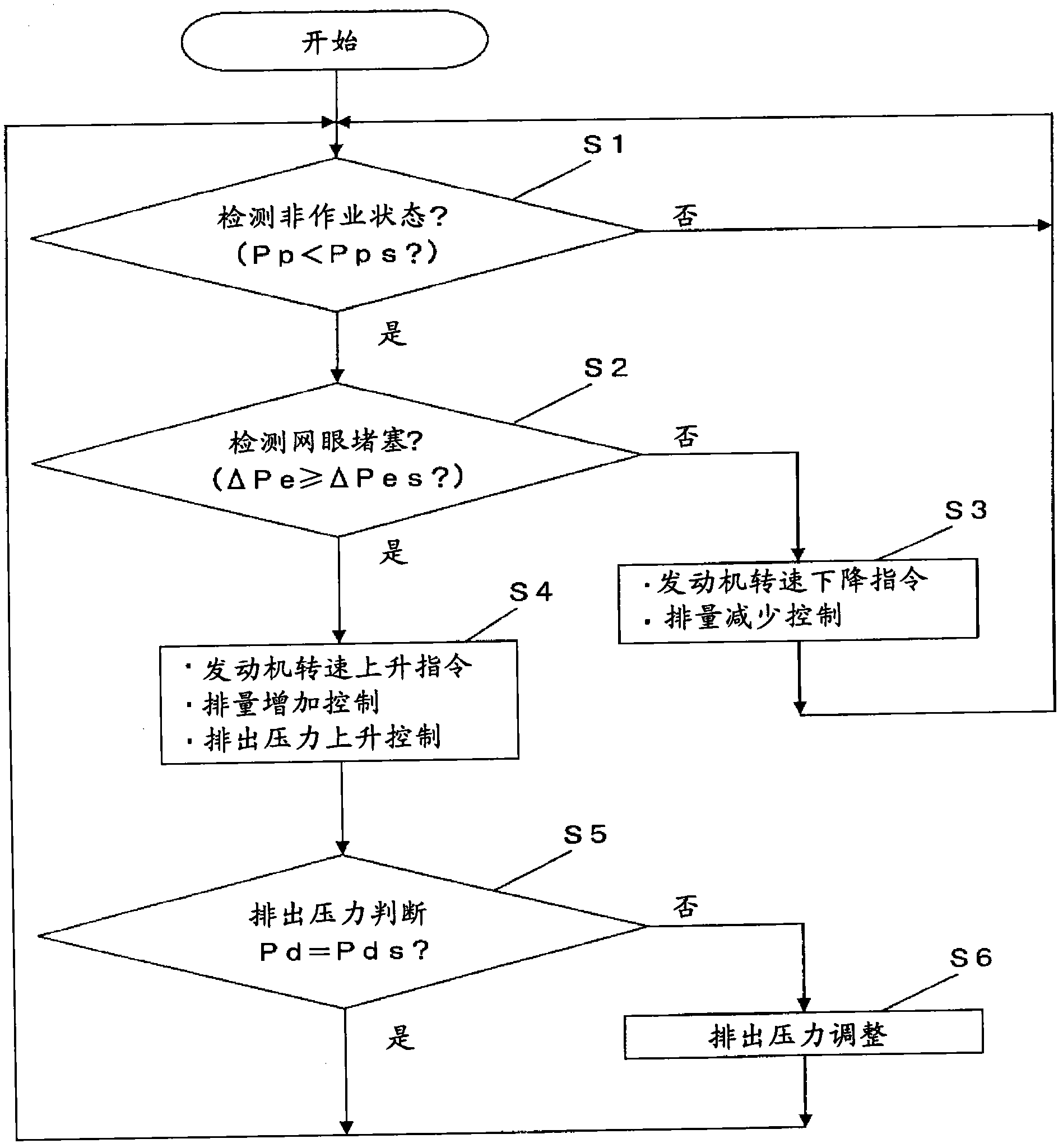
[0026] use figure 1 The hydraulic drive device of the hydraulic construction machine according to the first embodiment of the present invention will be described. figure 1 This is a hydraulic circuit diagram showing the configuration of the hydraulic drive device of the hydraulic construction machine according to the first embodiment of the present invention. figure 2 to represent the extraction figure 1 Block diagram of the electrical system of the hydraulic drive shown. image 3 to express figure 2 A flowchart showing the flow of actions in the controller.

[0027] like figure 1 As shown, the hydraulic drive device 1 of the hydraulic construction machine according to the first embodiment includes: an engine 2 (eg, a diesel engine) whose fuel injection amount is electronically controlled by an engine controller 3; A displacement type hydraulic pump 4 and a pilot pump 5 (fixed displacement type pump); and a hydraulic actuator 6 driven by hydraulic oil discharged from th...

no. 2 approach

[0061] use Figure 4 A hydraulic drive device of a hydraulic construction machine according to a second embodiment of the present invention will be described. Figure 4 It is a hydraulic circuit diagram which shows the structure of the hydraulic drive apparatus of the hydraulic construction machine concerning 2nd Embodiment of this invention.

[0062] like Figure 4 As shown, in the hydraulic drive device 30 of the second embodiment, the variable restrictor 19 is provided downstream of the actuator control control valve 7 on the flow path of the hydraulic oil discharged from the variable displacement hydraulic pump 4 side. The other configuration of the hydraulic drive device 30 is the same as that of the hydraulic drive device 1 of the first embodiment.

[0063] However, in the hydraulic drive device 30, the variable restrictor 19 adjusts the discharge passage of the hydraulic pressure from the actuator control control valve 7 to the hydraulic oil tank 8, even when the act...


PUM


Abstract

Provided is a hydraulic drive device of a hydraulic operating machine, wherein the discharge pressure can be reliably controlled at a predetermined value when the temperature of an exhaust gas is increased to a temperature necessary to burn particulate substances by increasing a load applied to an engine. A variable aperture (19) is controlled by a controller (14) and a control valve (20) for controlling a discharge pressure in a non-operation state of a hydraulic operating machine, to increase the discharge pressure of a variable displacement hydraulic pump (4), so that a load applied to an engine is increased to increase the temperature of an exhaust gas to a temperature necessary to burn particulate substances. In this respect, the controller (14) controls the control valve (20) for controlling a discharge pressure so that the discharge pressure detected by a discharge pressure sensor (21) matches with a predetermined basic discharge pressure. The basic discharge pressure is determined as a minimum pressure suitable for causing an exhaust gas to have a heat necessary to burn particulate substances.

Description

technical field [0001] The present invention is a hydraulic drive device of a hydraulic construction machine provided with an exhaust gas purification device that uses a filter to capture particulate matter in exhaust gas generated by incomplete combustion in an engine, and specifically relates to hydraulic In the non-working state of the construction machine, by increasing the engine output, the exhaust gas has the heat necessary for the combustion of particulate matter, and burns and removes the particulate matter in the filter of the exhaust gas purification device. Hydraulic drive device for hydraulic construction machinery. Background technique [0002] The hydraulic drive device of the hydraulic construction machine is provided with: an engine; a variable-capacity hydraulic pump that receives power transmission from the engine and is driven; a hydraulic actuator that is driven by working oil discharged from the variable-capacity hydraulic pump; Actuator control capable...

Claims


Application Information

Patent Timeline
Patent Type & Authority Applications(China)
IPC IPC(8): F04B49/00F01N3/02F04B49/08
CPCF02D2041/026F02D41/04F16H61/40F02D41/029F04B2205/05F04B49/08F01N3/021F04B17/05F01N3/023F01N2900/08F01N3/02F04B49/00
Inventor 中村刚志石川广二荒井康束田英信神谷象平
Owner HITACHI CONSTRUCTION MACHINERY CO LTD
Learn More