Impedance sensing systems and methods for use in measuring constituents in solid and fluid objects

A technology for sensing systems and test objects, applied in measurement devices, material impedance, instruments, etc., to solve problems such as multiple frequencies that no one has proposed

Active Publication Date: 2012-07-11
ADEM
View PDF17 Cites 12 Cited by
  • Summary
  • Abstract
  • Description
  • Claims
  • Application Information

AI Technical Summary

Problems solved by technology

[0029] The prior art proposes the use of multiple frequencies for determining chemical and/or physical properties by mea

Method used


Image

  • Impedance sensing systems and methods for use in measuring constituents in solid and fluid objects
  • Impedance sensing systems and methods for use in measuring constituents in solid and fluid objects
  • Impedance sensing systems and methods for use in measuring constituents in solid and fluid objects

Examples


example 1

[0120] Example 1: Regarding Bare Silicon Wafer and Covered with Test of the same wafer with thick aluminum film

[0121] Figure 15 An oscilloscope screenshot showing the impedance sensor output signal 151 in the 32-43 MHz frequency range with respect to a bare silicon wafer. The resonant frequency is 33.8MHz, and the resonant amplitude is 10067mV. Line 152 is the same impedance sensor on covered with Amplitude-frequency curve of the same wafer with thick aluminum film. In this case, the resonant frequency is 41MHz and the resonant amplitude is 1673mV. Comparing lines 151 and 152, it can be seen that the resonant frequency and, in particular, the voltage amplitude are significantly different. This example demonstrates the high sensitivity of the novel impedance sensing system according to the invention.

example 2

[0122] Example 2: Tests on Distilled and Tap Water Samples

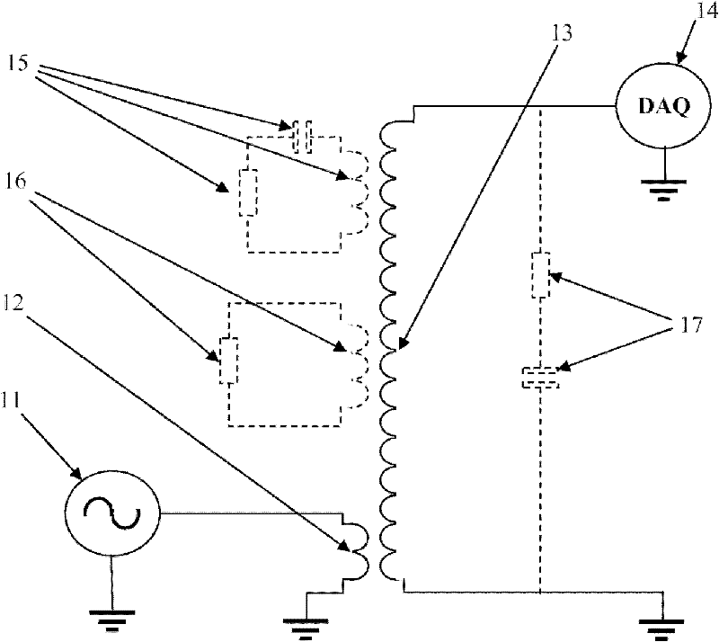
[0123] Figure 14 A test fixture is shown for calibrating and measuring variable concentrations of different constituents in a liquid (water as an example) in which an impedance sensor surrounds a small conduit-sampler (preferably made of Teflon).

[0124] Figure 16 Graphs showing test results under different conditions: 161 indicates when there is no liquid in the sampler, 162 indicates when the sampler is filled with distilled water, and 163 indicates when the sampler is filled with tap water. Distilled water showed only relatively small changes in sensor output magnitude compared to the blank sampler. Compared with the resonance frequency of 11MHz of distilled water, the resonance frequency shift of 12.5MHz of empty conduit is larger. However, both the amplitude and the resonant frequency of the tap water change significantly. This result can be understood because the resistivity of distilled water at 25°C is...

example 3

[0126] Example 3: Measurement of different NaCl concentrations in water

[0127] To determine the appropriate operating frequency for sodium chloride (NaCl) solutions in water, a preliminary study was performed by probing harmonic electromagnetic fields at a wide range of operating frequencies (20MHz, 70MHz, 370MHz, 480MHz). Frequencies around 20MHz show better results.

[0128] A frequency in the range of 17 to 20MHz was chosen for the impedance sensor. In the next example, the amplitude-frequency response of different concentrations of NaCl is measured.

[0129] Figure 17 The resulting graphs of these measurements are shown. As can be seen from the amplitude-frequency graphs, the solutions containing different concentrations of NaCl are clearly distinguished from each other. Distilled water (diamond fill) produces the highest amplitude at a frequency of about 19.6 MHz, the solution with the lowest concentration of NaCl produces a smaller amplitude than distilled water, a...


PUM


Abstract

A resonance type impedance sensor which is a multicoil open-core or air-core inductor, said sensor comprising at least two coils, one coil being an excitation coil connectable to at least one alternating current source with frequency sweep, another coil being a sensing coil connectable to at least one data processing system, wherein upon electrical connection to said current source, said excitation coil propagates an energy to said sensing coil, which generates a probing electromagnetic field, and wherein L, C, R parameters of said sensing coil are capable of providing resonance conditions for measuring of object under test impedance at predetermined frequency.

Description

[0001] related application [0002] This application claims priority to US Provisional Patent Application No. 61 / 244,584, filed September 22, 2009, entitled "Impedance sensors and their use for analyzing object's compositions," which is incorporated herein by reference in its entirety. [0003] Federally Sponsored Research Statement [0004] Not applicable [0005] Microfiche Addendum Reference [0006] Not applicable technical field [0007] The present invention relates to a new class of extremely sensitive electronic sensors capable of measuring physical properties, detecting and quantifying the composition of solids, bulk materials and liquids. More specifically, the novel sensor technology enables the measurement, detection, and quantification of material constituents regardless of their conductivity, transparency, and reflectivity under most environmental conditions where impedance resonance spectroscopy is applied. Provides a new real-time contactless method. Brie...

Claims


Application Information

Patent Timeline
IPC IPC(8): G01N27/02
CPCG01N27/023G01N27/02
Inventor 鲍里斯·凯斯尔尤里·尼科列诺克
Owner ADEM
Why Eureka
Try Eureka