Multi-manipulator multi-station combination flexible production line for energy-saving doors and windows and processing method of multi-manipulator multi-station combination flexible production line for energy-saving doors and windows

A flexible production line and manipulator technology, applied in metal processing, metal processing equipment, manufacturing tools, etc., can solve problems affecting large-scale, high-efficiency, high-quality plastic doors and windows, difficult to achieve modular combination, and unstable processing quality. Achieve the effect of improving processing quality and work efficiency, shortening processing cycle, and compact structure

Inactive Publication Date: 2012-07-18
JINAN DECA MASCH CO LTD
7 Cites 22 Cited by

AI-Extracted Technical Summary

Problems solved by technology

In the existing door and window manufacturing enterprises, four simple equipment with a single function are required for processing. The turnover of profiles among the equipment is very troublesome, and the processing efficiency of a single piece is low. There are errors in the positioning of each machine for the same profile, and th...

Method used

1. each processing unit is arbitrarily combined, selects different processing unit work to different processing technology, has not only improved working efficiency, shortened processing cycle, reduced production cost, and compact structure;
3. take conveying material as passage, there are a plurality of feeding manipulators, improved efficiency;
4. each working procedure is processed around profile processing, has reduced the time that material transfer delays, has improved efficiency;
Each processing content of nailing processing unit 6, sink processing unit 7, keyhole processing unit 8 and mounting hole processing unit 9 is realized by the processing equipment of each processing unit controlled by host computer 5, when pro...

Abstract

The invention discloses a multi-manipulator multi-station combination flexible production line for energy-saving doors and windows, which comprises a frame, two conveying passages, an upper computer, a feeding table, nailing units, water tank processing units, lock hole processing units and mounting hole processing units. The two conveying passages are disposed in parallel on the frame and pass through the whole production line. The processing units are sequentially disposed on the frame and on two sides of the conveying passages, and a manipulator and a compression device composed of an upper compression wheel and a lateral compression wheel are disposed between each two corresponding processing units. Process objects on the processing units are processed by processing equipment controlled by the upper computer, and the whole production line is controlled via intelligent production system integrated software CIMS (computer integrated manufacturing system). Compared with the prior art, the multi-manipulator multi-station combination flexible production line for energy-saving doors and windows has the advantages that automation level is high, the processing units are optionally combinable, a plurality of workpieces are processed simultaneously, time spent for conveying material is reduced, processing quality and operating efficiency are improved, processing cycle is shortened, production cost is lowered, and labor intensity is reduced.

Application Domain

Technology Topic

Image

  • Multi-manipulator multi-station combination flexible production line for energy-saving doors and windows and processing method of multi-manipulator multi-station combination flexible production line for energy-saving doors and windows
  • Multi-manipulator multi-station combination flexible production line for energy-saving doors and windows and processing method of multi-manipulator multi-station combination flexible production line for energy-saving doors and windows
  • Multi-manipulator multi-station combination flexible production line for energy-saving doors and windows and processing method of multi-manipulator multi-station combination flexible production line for energy-saving doors and windows

Examples

  • Experimental program(1)

Example Embodiment

[0031] The present invention will be further described in detail below with reference to the accompanying drawings and specific embodiments. The following description is only exemplary and does not limit the protection scope of the present invention.
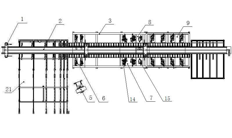
[0032] Such as figure 1 Shown is a schematic diagram of the structure of the present invention.
[0033] The invention includes an energy-saving door and window multi-manipulator multi-station combined flexible production line, including a nailing processing unit 6, a sink processing unit 7, a key hole processing unit 8, a mounting hole processing unit 9, an upper computer 5, and a conveying channel 2 for conveying profiles And the frame 3 for installing the processing unit and the conveying channel.
[0034] The nailing processing unit 6, the sink processing unit 7, the key hole processing unit 8, and the mounting hole processing unit 9 are arranged in sequence on both sides of the conveying channel 2 and the upper and lower frames 3 according to the shortest production cycle; A manipulator 1 and a pressing device are arranged between the units.
[0035] There are two conveying channels 2 which are arranged above the frame 3 in parallel, and the conveying channel 2 runs through the entire production line.
[0036] The processing contents of the nailing processing unit 6, the sink processing unit 7, the key hole processing unit 8 and the mounting hole processing unit 9 are realized by the upper computer 5 controlling the processing equipment of each processing unit. When the profile 22 is transported to a different processing unit , The corresponding processing unit equipment retreats after processing the profile 22, the manipulator 1 transports the profile 22 to the next processing unit to continue processing; through the control of the host computer 5, continuous processing of multiple materials can also be achieved, because each processing unit is set up There is a manipulator 1, so the processing of each processing unit can be carried out at the same time, which greatly improves the work efficiency.
[0037] The aforementioned control of each processing unit leaving the production line can also work independently.
[0038] The entire flexible production line is controlled by intelligent production system integration software (CIMS).
[0039] A loading platform 21 is also provided in front of the conveying channel 2.
[0040] Such as figure 2 Shown is a schematic diagram of the conveying channel structure of the present invention.
[0041] The conveying channel 2 is composed of a conveying table 11 and a manipulator 1 arranged above the frame 3.
[0042] The conveying table 11 is composed of a plurality of rollers 4 and side positioning rollers 12 arranged in sequence.
[0043] The manipulator 1 is arranged on both sides of a manipulator support 10 having a symmetrical structure, and the manipulator support 10 is installed on the frame 3 between the two conveying channels 2.
[0044] The nailing processing unit 6 includes a plurality of nailing heads arranged on the side frame 3 of the conveying table 11, and the shape to be shaped 22 is transported to the position by the robot 1, and the plurality of nailing heads nail the nails. After finishing, the nailing machine head returns.
[0045] Such as image 3 Shown is a schematic diagram of the arrangement of milling cutters of the sink processing unit of the present invention.
[0046] The sink processing unit 7 includes a fixed sink milling head 15 and a movable sink milling head 14 (such as figure 1 (Shown), the fixed flume milling head 15 and the movable flume milling head 14 are both provided with an upper flume milling head 23 and a plurality of flume milling cutters 13 arranged around the conveying channel. When the profile 22 is transported in place by the manipulator 1 , The upper head 23 of the milling water tank is moved to be close to the profile 22 and then feeds vertically, and the other water tank milling cutter 13 directly feeds to process the profile 22. After the processing is completed, the upper head 23 of the water milling tank moves back in translation.
[0047] Such as Figure 4 Shown is a schematic diagram of the tool arrangement of the key hole machining unit of the present invention.
[0048] The keyhole processing unit 8 includes a keyhole processing head 17 and a transmission groove processing head 16 arranged on the side of the conveying channel 2. When the profile 22 is transported into place by the robot 1, the keyhole processing head 17 is translated to approach the profile 22 Then it feeds vertically, and the transmission groove processing head 16 directly feeds to process the profile 22. After the processing is completed, the keyhole processing head 17 moves back in translation.
[0049] Such as Figure 5 Shown is a schematic diagram of the layout of the punching processing unit head of the present invention.
[0050] The punching processing unit 9 includes a punching head 18 arranged on the side of the conveying channel 2. When the profile 22 is transported into place by the manipulator 1, the punching head 18 directly punches holes. After the punching is completed, the punching head 18 returns .
[0051] Such as Image 6 Shown is a schematic diagram of the structure of the pressing device of each processing unit of the present invention.
[0052] The pressing device is composed of an upper pressing wheel 20 and a side pressing wheel 19.
[0053] The processing method of the present invention includes the following steps:
[0054] a. Preparation station: Use the integrated numerical control software to perform barcode recognition and scan on the processed profile 22, automatically read the content of the barcode, form the corresponding processing technology, select the processing unit participating in the work, and obtain the processing data of the profile 22;
[0055] b. Nailing: The profile 22 is transferred to the position of the conveying channel 2 through the loading table 21, and the manipulator 1 grabs the profile 22 and transports the profile 22 to the position of the nailing processing unit 6, and the nailing head tightens the profile 22. After nailing is completed, the profile 22 is transported by the manipulator 1 to the next processing unit;
[0056] c. Milling trough: When the profile 22 is nailed in the nailing processing unit 6, the movable milling trough head 14 is positioned according to the length of the profile 22. When the profile 22 is transported in place, the milling trough upper head 23 is translated and then fed vertically , The water tank milling cutter 13 is directly fed to process the profile 22. After the processing is completed, the upper head 23 of the milling tank is moved back and the profile 22 is transported to the next processing unit by the manipulator 1;
[0057] d. Punching the keyhole: When the profile 22 is transported to the keyhole processing unit 7, the keyhole processing head 17 is translated and then fed vertically. The transmission groove processing head 16 feeds directly to process the profile 22. After the processing is completed , The keyhole processing head 17 is moved back and the profile 22 is transported to the next processing unit by the manipulator 1;
[0058] e. Punching the mounting hole: the punching head 18 moves into position according to the determined distance between the punching heads 18, when the profile 22 is sent to the mounting hole processing unit 9, the side of the profile 22 is waiting to be punched The machine head 18 feeds and punches the profile 22, and returns after the punching, and the manipulator 1 transports the profile 22 out of the production line.
[0059] The working principle of the present invention:
[0060] Use the integrated numerical control software to read the code of the profile to form a corresponding processing technology to select the participating unit work, so that the feeding, processing and discharging cycles are optimized and interspersed.
[0061] Furthermore, the present invention can also be provided with multiple conveying channels 2 to form multiple production lines for simultaneous production, which greatly improves production efficiency.
[0062] The advantages of the present invention are:
[0063] 1. Various processing units can be combined at will, and different processing units can be selected to work for different processing techniques, which not only improves work efficiency, shortens the processing cycle, reduces production costs, and has a compact structure;
[0064] 2. Continuous processing of multiple materials at the same time improves efficiency;
[0065] 3. With the conveying material as the channel, there are multiple feeding manipulators, which improves the efficiency;
[0066] 4. The processing of each working procedure revolves around the processing of profiles, which reduces the delay in material delivery and improves efficiency;
[0067] 5. The processing method using this equipment improves processing quality and work efficiency, shortens the processing cycle, reduces production costs, and reduces labor intensity.
[0068] Compared with the prior art, the invention has the advantages of compact structure, high degree of automation, less labor, random combination of processing units, and simultaneous processing of multiple materials. The processing of each process is centered on profile processing, which reduces the delay in material delivery. The processing method of the invention improves the processing quality and work efficiency, shortens the processing cycle, reduces the production cost, and reduces the labor intensity.
[0069] The above description only explains the basic principles of the present invention. Those skilled in the art make many changes according to the prompts, such as the arrangement of the screw fastening head, the arrangement of the drilling head, the arrangement position of the milling head, and the milling machine The number of heads is adjusted, and the number of processed profiles can also be one, and the number of corresponding processing heads is correspondingly reduced, etc., which cannot be used to limit the scope of protection of the present invention. All are within or equivalent to the scope of the present invention. The changes within are all surrounded by the present invention.

PUM

no PUM

Description & Claims & Application Information

We can also present the details of the Description, Claims and Application information to help users get a comprehensive understanding of the technical details of the patent, such as background art, summary of invention, brief description of drawings, description of embodiments, and other original content. On the other hand, users can also determine the specific scope of protection of the technology through the list of claims; as well as understand the changes in the life cycle of the technology with the presentation of the patent timeline. Login to view more.

Similar technology patents

Municipal solid waste comprehensive treatment and recycling device

InactiveCN102039303AReduce the spread of odorsCompact structureSievingScreeningWater pipeMetal recycling
Owner:HENAN AOSI ENVIRONMENTAL PROTECTION MACHINE

Classification and recommendation of technical efficacy words

  • Compact structure
  • High degree of automation
Why Eureka
Try Eureka