Continuous sequencing-batch aerobic subsequent treatment section influent water flow control device and flow buffer method

A technology of flow control device and treatment section, applied in chemical instruments and methods, water/sewage multi-stage treatment, water/sludge/sewage treatment, etc. To solve problems such as treatment effect, to achieve the effect of reducing drug consumption, reducing frequent adjustment, and convenient follow-up processing

Active Publication Date: 2013-06-05
INST OF CHEM IND OF FOREST PROD CHINESE ACAD OF FORESTRY
View PDF4 Cites 0 Cited by
  • Summary
  • Abstract
  • Description
  • Claims
  • Application Information

AI Technical Summary

Problems solved by technology

However, the UNITANK system often needs to carry out three-stage coagulation and dosing treatment in the follow-up, the fluctuation of water volume will directly affect the treatment effect, and more automatic control valves and corresponding pipelines must be added, while power consumption

Method used


Image

  • Continuous sequencing-batch aerobic subsequent treatment section influent water flow control device and flow buffer method
  • Continuous sequencing-batch aerobic subsequent treatment section influent water flow control device and flow buffer method
  • Continuous sequencing-batch aerobic subsequent treatment section influent water flow control device and flow buffer method

Examples


Embodiment 1

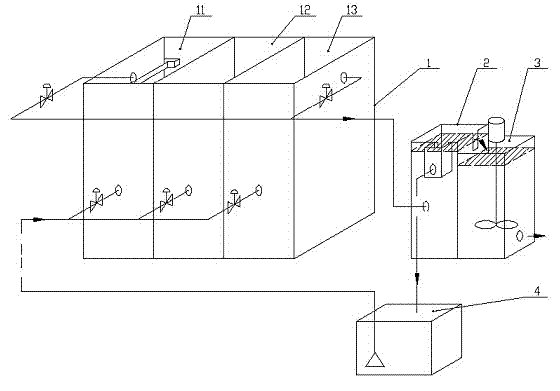
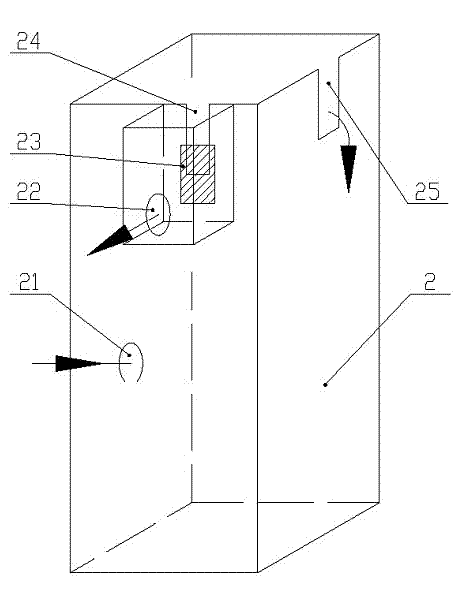
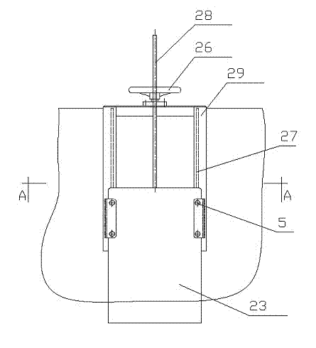
[0020] like figure 1 , 2 , 3, the UNITANK aerobic pool 1 is subsequently connected to the buffer pool 2 and the coagulation pool 3, the effluent from the functional weir 24 of the buffer pool 2 flows back to the sump 4, and the waste water from the sump 4 enters the system through the lift pump, and the UNITANK pool Including side pool 11, middle pool 12 and side pool 13, buffer pool 2 includes water inlet 21, functional weir 24 and water outlet 25, functional weir 24 is provided with a sealing gate 23 to control the elevation of the weir mouth, and the outlet water of the weir mouth is collected by the collection tank through The return port 22 is discharged, and the outlet water from the buffer tank 2 enters the coagulation tank 3 . The sealing gate 23 is inserted into the gate seat 29, the screw rod 28 is connected to the gate plate 23, and the rotatable handwheel 26 is fixed on the gate seat 29. The handwheel 26 cooperates with the threaded mandrel 28, so that the gate ca...

Embodiment 2

[0023] like figure 1 , 2 , 3, UNITANK pool 1 is subsequently connected to buffer pool 2 and coagulation pool 3 in turn, the effluent from the functional weir 24 of buffer pool 2 flows back to sump 4, and the waste water from sump 4 enters the system through a lift pump, and the UNITANK pool includes side The pool 11, the middle pool 12 and the side pool 13. The buffer pool 2 includes a water inlet 21, a functional weir 24 and a water outlet 25. The functional weir 24 is provided with a sealing gate 23 to control the elevation of the weir mouth. The outlet water of the weir mouth is collected by the collection tank through the return port 22 is discharged, and the effluent from the buffer tank 2 enters the coagulation tank 3.

[0024] In a design water volume of 200m 3 In the waste water treatment system per hour, the buffer tank 2 is designed to be 1500mm×1500mm×5000mm, the diameter of the water inlet 21 is DN300mm, the width of the water outlet 25 is 100mm, and the width of...


PUM


Abstract

The invention discloses a continuous sequencing-batch aerobic subsequent treatment section influent water flow control device and a flow buffer method. The flow control device comprises an aerobic pool and a coagulation pool, wherein the aerobic pool comprises a water inlet, a water outlet and a buffer pool of which the liquid level height is lower than the buffer pool of the aerobic pool water outlet; the buffer pool at least comprises a water inlet, a water outlet and a functional weir port; the functional weir port is provided with a seal valve plate for regulating the height of the functional weir; the water outlet of the aerobic pool is connected with the water inlet of the buffer pool; the coagulation pool is positioned downstream the water outlet of the buffer pool; and the effluent water of the functional weir of the buffer pool is connected with the water inlet of the aerobic pool through a return pipe. The buffer pool is arranged behind the effluent water of the aerobic pool, so that most excess effluent water of the aerobic pool flows out from the functional weir, thereby ensuring that the wastewater can stably enter the subsequent treatment work section, and avoiding the defects of unstable operation, high chemical consumption and the like in the subsequent treatment work section due to sudden increase of the wastewater flow of the aerobic pool.

Description

technical field [0001] The invention belongs to the technical field of water supply and drainage of civil engineering, and in particular relates to a flow control device and a buffering method for water inflow in a continuous batch type aerobic subsequent treatment section. Background technique [0002] In water supply and drainage treatment, in order to maintain the treatment effect or maintain the stability of the dosing process, a stable flow of wastewater to be treated is often required. The feedback control method of flowmeters and automatic control valves is widely used in projects. This method is mature and reliable, but it is The flow restriction control method is very suitable when the wastewater enters the treatment system, but after entering the system, the wastewater often flows between the treatment facilities in a self-flow manner. If it is restricted, it will cause the accumulation of wastewater in a certain section. For example, in UNITANK (a type of continuo...

Claims


Application Information

Patent Timeline
Patent Type & Authority Patents(China)
IPC IPC(8): C02F9/14
Inventor 盘爱享房桂干邓拥军丁来保施英乔韩善明焦健李红斌梁芳敏沈葵忠李萍
Owner INST OF CHEM IND OF FOREST PROD CHINESE ACAD OF FORESTRY
Why Eureka
Try Eureka