Multi-magnetic field magnetron sputtering cathode

A magnetron sputtering, multi-magnetic field technology, applied in the field of magnetron sputtering cathodes with multi-magnetic field distribution, can solve the problem of small uniform magnetic field range, limiting the effective sputtering length and sputtering time of single rectangular cathode magnetron sputtering coating, Target bombardment area concentration and other problems, to achieve the effect of wide application, increase the effective coating distance and coating time

Inactive Publication Date: 2012-07-18
王正安
View PDF0 Cites 10 Cited by
  • Summary
  • Abstract
  • Description
  • Claims
  • Application Information

AI Technical Summary

Problems solved by technology

On the one hand, the uniform range of the magnetic field under this design scheme is small, which directly leads to the concentration of the bombardment area of ​​the target and the low utilization rate; on the other hand, the magnetic field ring is distributed along the length direction of the rectangular cathode. In order to obtain better coating uniformity, The movement direction of the substrate is along the width direction of the cathode, which greatly limits the effective sputtering length and sputtering time of the single rectangular cathode magnetron sputtering coating, which in turn limits the application field of the single cathode sputtering system

Method used


Image

  • Multi-magnetic field magnetron sputtering cathode
  • Multi-magnetic field magnetron sputtering cathode
  • Multi-magnetic field magnetron sputtering cathode

Examples


Embodiment Construction

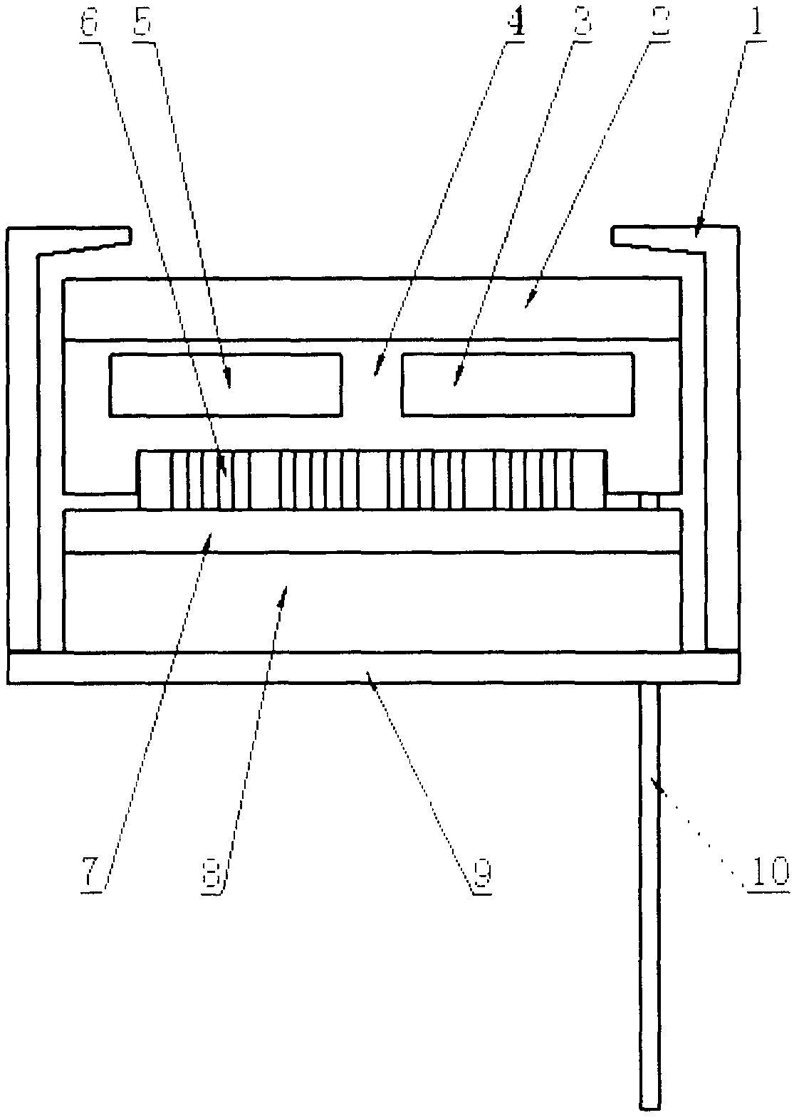
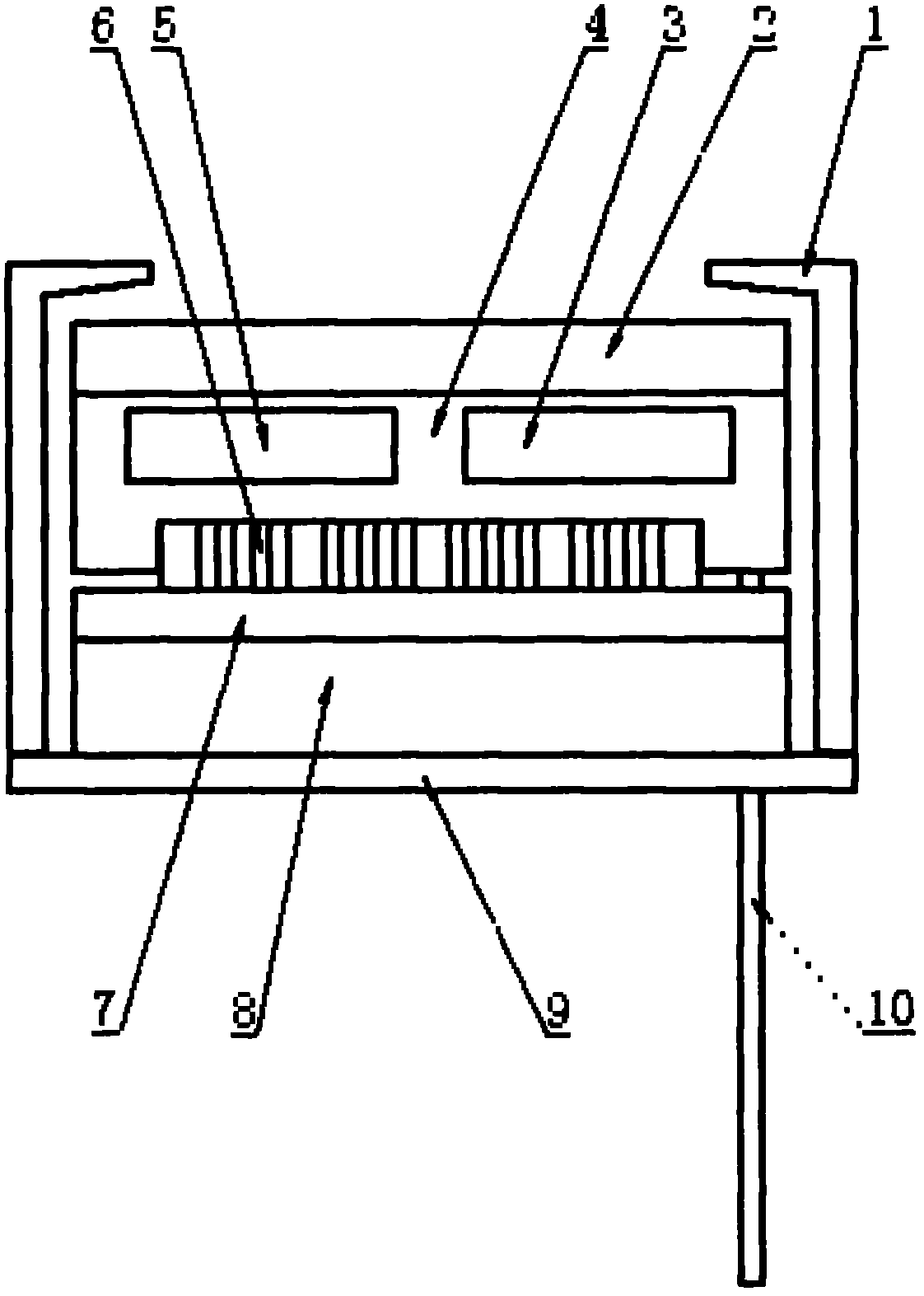
[0019] The present invention will be further described below in conjunction with accompanying drawing

[0020] As shown in the figure, the cathode involved in the present invention includes a cathode base plate 9 supporting the overall structure, a coaxial cable 10 for transmitting power source power, a polytetrafluoroethylene insulator 8, a yoke iron 7 for limiting the magnetic circuit, a magnet 6, and a cathode body 4 and the integrated cooling units 3 and 5, the target 2 and the anode cover 1. The insulator 8 is fixed on the cathode bottom plate 9; the cathode main body 1 has a cold water tank (water inlet tank 3 and water outlet tank 5) inside to form a cooling unit; the magnets 6 are directly arranged on the yoke iron 7 to form a magnetic field unit, and the whole is fixed on the cathode main body 1, the front end of the cathode main body 4 is directly in contact with the sputtering target 2, placed on the insulator 8 as a whole, and insulated from the cathode base plate ...


PUM

PropertyMeasurementUnit
thicknessaaaaaaaaaa
thicknessaaaaaaaaaa
thicknessaaaaaaaaaa

Abstract

The invention discloses a multi-magnetic field magnetron sputtering cathode. The cathode is characterized in that: a plurality of magnet units are arranged and combined to form a multi-magnetic field coupled planar sputtering cathode, and are arranged along the length direction of a rectangular cathode. Compared with the prior art, the cathode has the advantages that: effective sputtering time of a single rectangular planar cathode sputtering system is greatly prolonged, effective deposition distances of the system is greatly increased, and the uniformity of a planar cathode sputter coating and the utilization rate of a planar target are effectively improved. The whole cathode is simply designed and has a simple preparation process, so that a planar cathode coating mode has a wide application field in industrial production.

Description

[technical field] [0001] The invention relates to a magnetron sputtering cathode, in particular to a magnetron sputtering cathode with high target utilization and multi-magnetic field distribution [Background technique] [0002] Magnetron sputtering is a vacuum coating technology using electric and magnetic fields. In the magnetic field, moving electrons are affected by Lorentz force. Under the joint action of electric field force and Lorentz force, electrons will produce spiral motion. The moving path becomes longer, which increases the number of collisions with working gas molecules, increases the plasma density, and thus greatly increases the magnetron sputtering rate, and works at a lower sputtering voltage and pressure, reducing the risk of film contamination Tendency; on the other hand, it increases the energy of the atoms incident on the surface of the substrate, and improves the quality of the film to a large extent. At the same time, electrons that have lost energy...

Claims


Application Information

Patent Timeline
Patent Type & Authority Applications(China)
IPC IPC(8): C23C14/35
Inventor 王正安
Owner 王正安
Why Eureka
Try Eureka