Method for improving optical element additional surface shape caused by force of gravity, and clamping system thereof

An optical element and surface shape technology, applied in the control of the additional surface shape of ultra-thin optical elements, the additional surface shape of large-diameter ultra-thin transmissive optical elements, and the field of clamping systems, which can solve the problem of surface shape changes without optimization and control. , complex control, large additional surface shape and other problems, to achieve the effect of improving additional surface shape, simple theory, and small residual stress

Inactive Publication Date: 2012-07-18
LASER FUSION RES CENT CHINA ACAD OF ENG PHYSICS +1
View PDF1 Cites 24 Cited by
  • Summary
  • Abstract
  • Description
  • Claims
  • Application Information

AI Technical Summary

Problems solved by technology

However, in the implementation process of this method, when the KDP crystal is placed obliquely, there is no optimization and control effect on the surface shape change caused by gravity, and it is easy to cause a larger additional surface shape. Moreover, because the four sides of the clamping system have three Twelve rubber nails, the control of which is also very complicated

Method used


Image

  • Method for improving optical element additional surface shape caused by force of gravity, and clamping system thereof
  • Method for improving optical element additional surface shape caused by force of gravity, and clamping system thereof
  • Method for improving optical element additional surface shape caused by force of gravity, and clamping system thereof

Examples


Embodiment 1

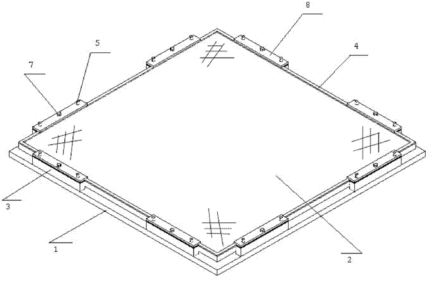
[0059] In this embodiment, as figure 1 and figure 2 The shown structure of the clamping system is used to improve the additional surface shape of the large-aperture ultra-thin KDP crystal 2 caused by gravity, according to figure 1 Install the clamping system as shown in and adjust the components.

[0060] For 330×330mm 2 Diameter, KDP crystal with a thickness of 10mm, its effective aperture is not less than 300mm, each part in the clamping system is made of stainless steel, the 330×330mm 2The additional surface shape in the effective clear aperture of the KDP crystal with a diameter of 10mm and a thickness of 10mm is used as the optimized objective function. Through the calculation and simulation of the finite element analysis software ANSYS, the solution that the change value of the additional surface shape is relatively the smallest when it is placed at different angles to achieve equilibrium is obtained. According to this minimum solution, it is determined that the leng...

Embodiment 2

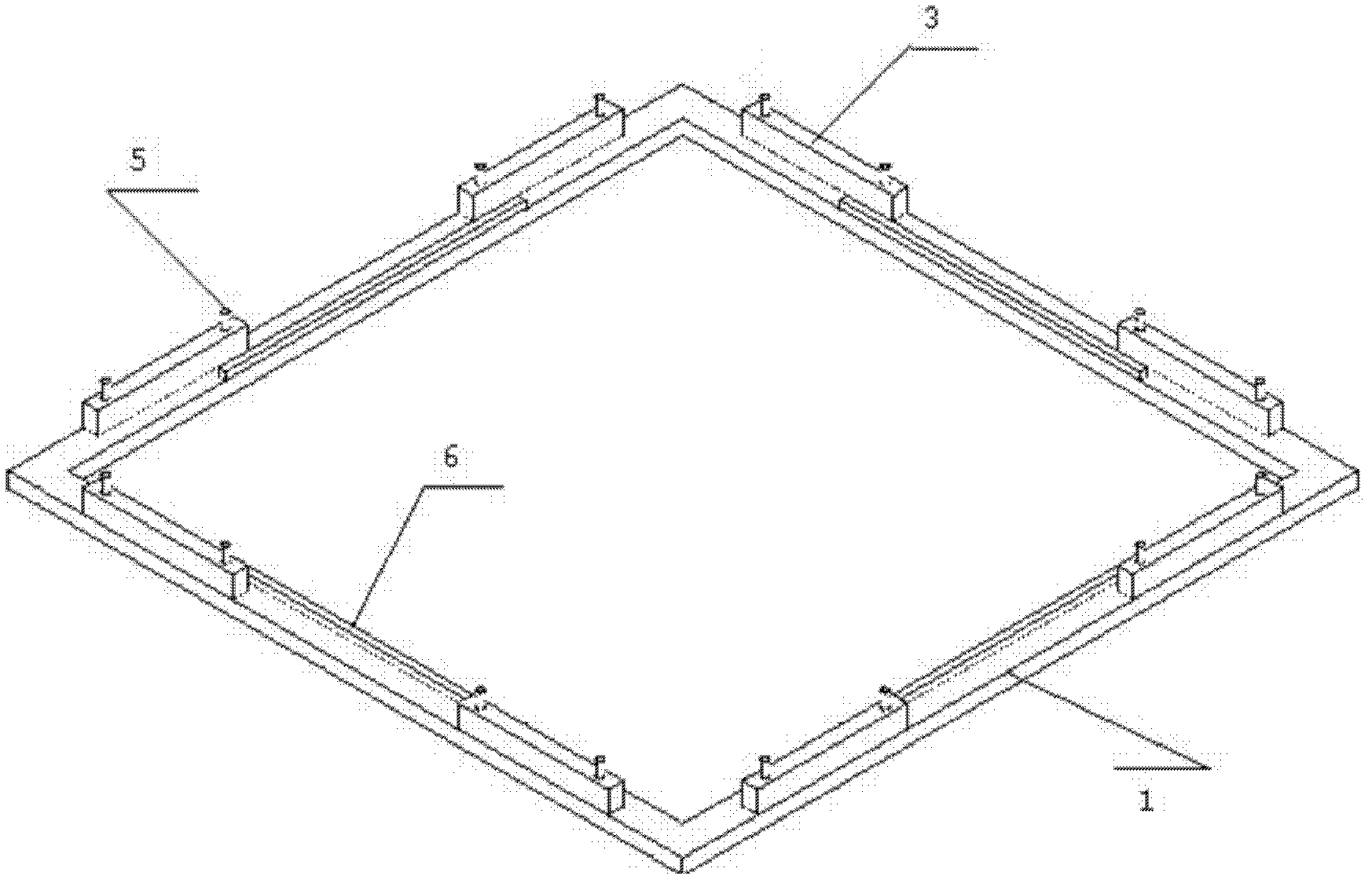
[0063] In this embodiment, as figure 1 and figure 2 The shown structure of the clamping system is used to improve the additional surface shape of the large-aperture ultra-thin KDP crystal 2 caused by gravity, according to figure 1 Install the clamping system as shown in and adjust the components.

[0064] For 430×430mm 2 For a KDP crystal with a caliber and a thickness of 10mm, its effective aperture is not less than 400mm, and the components in the clamping system are made of stainless steel, and the 430×430mm 2 The additional surface shape in the effective clear aperture of the KDP crystal with a diameter of 10mm is used as the optimized objective function, and the solution that the value of the additional surface shape change is relatively the smallest when it is placed at different angles to achieve equilibrium is obtained through the calculation and simulation of the finite element analysis software ANSYS According to this minimum solution, it is determined that the l...

Embodiment 3

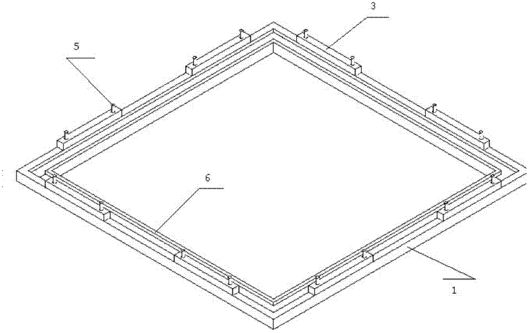
[0067] In this embodiment, as figure 1 and image 3 The shown structure of the clamping system is used to improve the additional surface shape of the large-aperture ultra-thin KDP crystal 2 caused by gravity, according to figure 1 Install the clamping system as shown in and adjust the components.

[0068] For 330×330mm 2 For a KDP crystal with a caliber and a thickness of 10mm, its effective aperture is not less than 300mm. The components of the clamping system are made of stainless steel. The 330×330mm 2 The additional surface shape in the effective clear aperture of the KDP crystal with a diameter of 10mm is used as the optimized objective function, and the solution that the value of the additional surface shape change is relatively the smallest when it is placed at different angles to achieve equilibrium is obtained through the calculation and simulation of the finite element analysis software ANSYS According to this minimum solution, it is determined that the thickness ...


PUM


Abstract

The invention relates to a method for improving an optical element additional surface shape caused by force of gravity, and a clamping system thereof. The method utilizes the lever principle, and aims at a heavy-calibre ultrathin transmission-type optical element under the condition of effective clear aperture. Through the clamping system provided by the invention, finite-element analysis software is adopted to carry out modeling simulation and determine lengths, widths and positions of a support strip and a pressure strip as well as force applied onto the pressure strip in the clamping system when the optical element is placed to be balanced at different work gestures and has the minimum additional surface shape change. Through changing the force applied onto the pressure strip, the optical element in the clamping system can have the balanced state at different work gestures, so as to achieve the purpose of improving the optical element additional surface shape caused by force of gravity. The clamping system for realizing the method includes a base, the support strip, a baffle plate, the pressure strip, the optical element, as well as an external wrench and a heavy-calibre interferometer. The method and the clamping system provided by the invention can improve the additional surface shape of the heavy-calibre ultrathin transmission-type optical element caused by force of gravity.

Description

technical field [0001] The invention relates to a method for controlling the additional surface shape of an ultra-thin optical element, in particular to a method for improving the additional surface shape of a large-diameter ultra-thin transmissive optical element caused by gravity by using the principle of leverage, and a clamping system for realizing the method , which belongs to the field of additional surface shape control of optical components. Background technique [0002] With the continuous development of high-power laser technology, people's requirements for the light collection ability, resolution ability and transmission ability of the laser system are also constantly improving. Since the peak laser power is limited by the damage threshold of the optical components of the system, the resolving power is proportional to the size of the primary mirror and other factors, resulting in an increasing aperture of the optical components. The increase in the aperture of th...

Claims


Application Information

Patent Timeline
Patent Type & Authority Applications(China)
IPC IPC(8): G02B27/00G02B7/00
Inventor 熊召张彬贾凯曹庭分徐旭袁晓东郑万国贺少勃崔凯洪徐攀叶荣吴双
Owner LASER FUSION RES CENT CHINA ACAD OF ENG PHYSICS
Why Eureka
Try Eureka