Embedded type wiring terminal sealing cover for large aluminium electrolytic capacitors

A technology for aluminum electrolytic capacitors and terminals, applied in capacitor terminals, capacitor shells/packages, and capacitor components, etc., which can solve the problems of high positive and negative short-circuit risks of capacitors, increase of equivalent series inductance of capacitors, and increase of loop space, etc.

Inactive Publication Date: 2012-07-18
周旺龙
View PDF0 Cites 8 Cited by
  • Summary
  • Abstract
  • Description
  • Claims
  • Application Information

AI Technical Summary

Problems solved by technology

When the pressure valve is activated to release the pressure, the electrolytic solution charged with the negative electrode will splash out from the pressure release port, so the capacitor has a very high risk of positive and negative short circuit
Moreover, in order to prevent creepage between the positive and negative terminals, it is usually necessary to set an anti-creepage safety distance of about 10mm between the positive and negative terminal posts according to the operating voltage, which increases the loop space and increases the capacitor's load. Effective Series Inductance (ESL) Value

Method used


Image

  • Embedded type wiring terminal sealing cover for large aluminium electrolytic capacitors
  • Embedded type wiring terminal sealing cover for large aluminium electrolytic capacitors
  • Embedded type wiring terminal sealing cover for large aluminium electrolytic capacitors

Examples


Embodiment 1

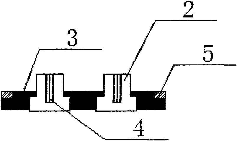
[0015] Example 1: Increase the diameter of the wiring terminal 2 inside the insulating material body 3 of the sealing terminal cover, reduce the distance between the positive and negative terminals, and start the pressure valve 1 for the wiring terminal post 2 protruding from the sealing insulating material body 3 Cover with the same insulating material as the sealing insulating material plate body 3 within a safe distance. It should be noted that the surface distance between the positive and negative terminal 2 should be greater than the creepage distance. As a result, the enclosed space between the terminal posts is reduced, which reduces the equivalent series inductance (ESL) value. And remove the risk of positive and negative short circuit caused by splashing electrolyte when the pressure valve is activated (such as Figure 2a , Figure 2b ).

Embodiment 2

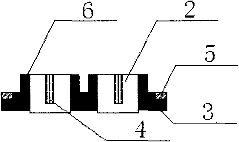
[0016] Example 2: Increase the diameter of the terminal 2 inside the insulating material body 3 of the sealing terminal cover plate, reduce the distance between the positive and negative terminals, and set the connection terminal 2 protruding from the insulating material body 3 of the sealing terminal in the safety room where the pressure valve 1 is activated. The same insulating material as the board body is used for overall coating within the distance. It should be noted that in order to ensure that the surface distance between the positive and negative terminals 2 is greater than the creepage distance, the insulating material covering body 6 is exposed or protruded from the terminal post 2. The diameter of the surface part needs to be reduced to ensure that the surface distance between the positive and negative terminals 2 on the surface is greater than the creepage distance. As a result, the enclosed space between the terminal posts is reduced, which reduces the equivalent ...


PUM


Abstract

Disclosed is an embedded type wiring terminal sealing cover for large aluminium electrolytic capacitors, wherein an insulating material which is identical with a terminal cover and integrated with an insulating terminal block is used for coating a naked positive wiring terminal post and a naked negative wiring terminal post respectively or integrally, or the wiring terminal posts are embedded into the insulating material body of the cover, so that the distance between the positive wiring terminal post and the negative wiring terminal post in the insulating material is reduced, the area of a loop is reduced, the equivalent series inductance (ESL) value is reduced, and at the same time, the risk that the positive pole and the negative pole are short-circuited caused by an electrolyte splashed during release of a pressure valve is eliminated.

Description

Technical field: [0001] The invention relates to a sealing terminal cover plate with low inductance and anti-short circuit function for large aluminum electrolytic capacitors. Background technique: [0002] Large-scale aluminum electrolytic capacitors are composed of a core package composed of inner positive and negative aluminum foils and electrolytic paper curls, an outer cylindrical aluminum shell, and a sealing cover plate with positive and negative terminals. The positive and negative aluminum foils that are crimped to form the core package and the corresponding positive and negative terminals on the inside of the sealing cover are connected with aluminum lead-out bars. [0003] In order to prevent the capacitor from being extremely damaged under overload conditions such as overvoltage and overcurrent, there is an internal pressure release guide hole, that is, an explosion-proof valve or a pressure valve, on the sealed terminal cover plate far from the terminal post, us...

Claims


Application Information

Patent Timeline
Patent Type & Authority Applications(China)
IPC IPC(8): H01G9/08H01G9/008H01G9/12
Inventor 周旺龙
Owner 周旺龙
Why Eureka
Try Eureka