
Photovoltaic honeycomb component module with heat collecting pipe

A technology of honeycomb components and heat pipes, which is applied in the field of photovoltaic heat pipe honeycomb component modules, can solve the problems of unguaranteed safety, increased cost, peeling off, etc., and achieve the effect of reducing material and labor costs, enhancing reliability, and good flatness

Active Publication Date: 2013-01-23
合肥微纳电工有限公司
View PDF3 Cites 0 Cited by
  • Summary
  • Abstract
  • Description
  • Claims
  • Application Information

AI Technical Summary

Problems solved by technology

The technical solution of this patent is simply to bond and combine the finished photovoltaic module and the finished aluminum honeycomb panel. Thick photovoltaic modules, photovoltaic modules and material peeling off will be more serious, and their safety cannot be guaranteed in engineering applications. The current building exterior walls are no longer allowed to use adhesive building materials; The junction box and its bypass protection diode are necessary and important parts, which are usually bonded on the back of the photovoltaic module. According to the structure of the above patent, only the junction box and the bypass diode are placed outside the solar honeycomb panel. The first solar honeycomb panel lacks integrity; if it is to be placed in the solar honeycomb panel, there will be a problem of heat dissipation of the diodes in the junction box; fourth: the patent "set the solar panel on the upper aluminum alloy panel, and the solar panel and the upper aluminum alloy panel There is a third layer of glue between them. The upper aluminum alloy panel is the most expensive material in the aluminum honeycomb panel. This combination not only causes the problem of material peeling off, but also directly leads to an increase in cost; fifth: it cannot be used for heating

Method used


Image

  • Photovoltaic honeycomb component module with heat collecting pipe
  • Photovoltaic honeycomb component module with heat collecting pipe
  • Photovoltaic honeycomb component module with heat collecting pipe

Examples


Embodiment Construction

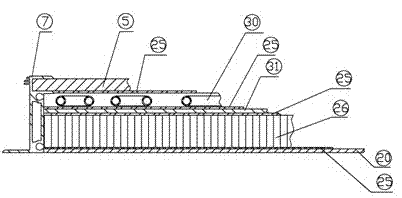
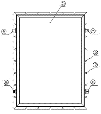
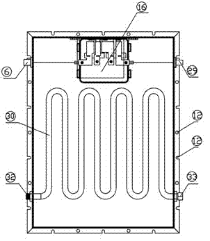
[0025] like Figure 1-4 As shown, it includes a photovoltaic module composed of a photovoltaic panel 5, a connector and a junction box 27. The lower layer of the photovoltaic panel 5 is a solar heat collector 30, an aluminum honeycomb core 26, and a back aluminum plate 20 (rust steel plate can also be used). The main structure of the component module is formed by bonding the hot-melt adhesive film 25 ; the aluminum alloy frame 7 is arranged around the main structure of the component module; the aluminum alloy frame 7 is provided with an installation hole 12 . The connectors are the positive connector 6 and the negative connector 29, and the two ports of the solar collector tube 30 are provided with a collector tube outlet joint 32 and a heat collector tube inlet joint 33, which are respectively located on both sides of the component module; the junction box is built into the honeycomb core layer middle.

[0026] Two layers of hot-melt adhesive films 25 are arranged between th...


PUM


Abstract

A photovoltaic heat pipe cell component module comprising a photovoltaic component consisting of a photovoltaic plate (5), connectors (6, 29), and junction boxes (13, 16), the lower layer of the photovoltaic plate (5) being, in order, a solar energy heat collecting tube (30), a cell core layer (26), and a back plate (20), connected to one another by a thermal bonding film (25), and all together forming the main body structure of the component module; disposed along the circumference of the main body structure of the component module is an aluminum alloy frame (7); the connectors (6, 29) are a positive connector (6) and a negative connector (29); disposed on either end of the solar energy heat collecting tube (30) are an inlet interface (33) and an outlet interface (32), each disposed at one end of the component module; the junction boxes (13, 16) are disposed in the cell core layer (26). The problem of peeling and detaching of photovoltaic components and material, and diode heat dissipation inside of a junction box are better solved. The module has a standardized design, is highly integral, easy to install, and relatively low in manufacturing cost.

Description

technical field [0001] The invention relates to a novel photovoltaic building material, in particular to a photovoltaic heat pipe honeycomb component module, which can be used for solar power generation and heat collection, and can also be used as a building material for the top floor or wall of a building. Background technique [0002] Due to the energy crisis and the need for sustainable development, photovoltaic power generation, especially photovoltaic building integration, is one of the important technical means. The optimal combination of photovoltaics and buildings has a broad market, and photovoltaic honeycomb modules will be an important choice. In the solar photovoltaic cells in the prior art, the photovoltaic panels are laid on the top floor of the building using a fixing frame, and the photovoltaic panels are connected by cables. This installation method is costly and complicated. However, the honeycomb panels in the prior art are mainly used in the constr...

Claims


Application Information

Patent Timeline
Patent Type & Authority Patents(China)
IPC IPC(8): H01L31/048H01L31/052H01L31/058E04C2/292E04C2/36E04D13/18H01L31/0525H02S40/34
CPCY02E10/60H01L31/052Y02E10/44Y02B10/20F24J2002/0092H01L31/0486H01L31/058H01L31/048Y02B10/12F24J2/32Y02E10/50F24S10/95F24S2020/17H02S40/345H02S40/42Y02B10/10
Inventor 余晓东
Owner 合肥微纳电工有限公司
Learn More