Power module group of high-power current-converting equipment

A technology of equipment power and power modules, which is applied to output power conversion devices, electrical components, cooling/ventilation/heating transformation, etc., can solve the problems of large energy consumption and long wind range, and achieve low energy consumption of air cooling The effect of short distance and small temperature difference

Inactive Publication Date: 2012-07-18
上方能源技术(杭州)有限公司
View PDF4 Cites 11 Cited by
  • Summary
  • Abstract
  • Description
  • Claims
  • Application Information

AI Technical Summary

Problems solved by technology

[0004] The above two power cabinets are generally composed of multiple power monomers stacked, and each power monomer realizes the ABC three-phase conversion, and often includes several IGBTs, a stacked busbar, a radiator and several Capacitors, in this system, the ABC three-phase conversion will be output th

Method used


Image

  • Power module group of high-power current-converting equipment
  • Power module group of high-power current-converting equipment
  • Power module group of high-power current-converting equipment

Examples


Embodiment 1

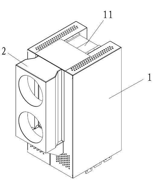
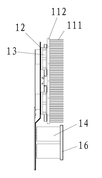
[0039] Embodiment 1: as Figures 1 to 3 As shown, a power module group of high-power converter equipment includes two power modules 1 distributed side by side. The power module 1 includes a casing 15, a laminated busbar 12 fixed to the inner wall of the casing 15, The upper IGBT component 13, the capacitor support plate 16 fixed on the other inner wall of the housing 15, the capacitor component 14 fixedly connected between the laminated busbar 12 and the capacitor support plate 16, and the IGBT component 13 are fixedly connected to the IGBT component 13 Radiator 11 for dissipating heat.

[0040] The casing 15 is located at the position of the capacitor assembly 14 and is provided with cooling holes 151 for the cooling of the capacitor assembly 14 . In order to achieve a better heat dissipation effect, a fan can also be fixed at the position of the casing 15 provided with the cooling holes 151 .

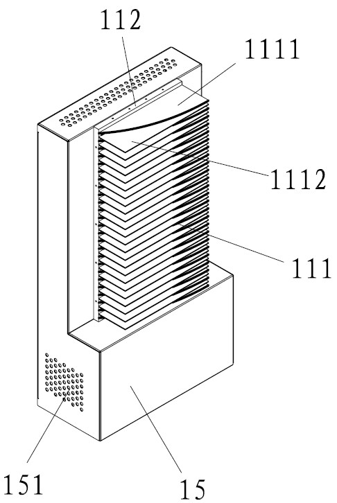
[0041]The heat sink 11 includes a heat dissipation plate 112 fixedly connected t...

Embodiment 2

[0043] Embodiment 2: The difference with Embodiment 1 is that, as Figure 4 As shown, the side of the fan fin 1111 that is farther away from the heat dissipation plate 112 in the length direction includes a straight section 11111 parallel to the heat dissipation plate 112, and a slow temperature section 11112 where the distance between the fan fin 1111 and the heat dissipation plate 112 gradually decreases along the wind direction of the fan 2; The slow temperature section 11112 is arc-shaped.

Embodiment 3

[0044] Embodiment 3: The difference from Embodiment 1 is that the heat dissipation fins 111 are fan fins 1111, and the distance between the side of the fan fins 1111 that is farther away from the heat dissipation plate 112 in the length direction and the heat dissipation plate 112 is gradually along the wind direction of the fan 2. increase; and the side of the fan fin 1111 that is farther away from the heat dissipation plate 112 in the length direction is arc-shaped.


PUM


Abstract

The invention relates to large three-phase current-converting equipment, in particular relates to a power module group of high-power current-converting equipment. The invention is realized by the following technical scheme that the power module group comprises two power modules with radiators, and a fan for simultaneous radiation of the two radiators; each radiator comprises radiating fins of the power modules; the radiating fins of the two radiators are distributed in opposite direction and in a side-by-side manner; and the air direction of the fan is along the length direction of the radiating fins. The module group has the advantages of a simple air-cooling structure and low energy consumption.

Description

technical field [0001] The invention relates to large-scale three-phase converter equipment, in particular to a power module group of high-power converter equipment. Background technique [0002] The high-power inverter system in the prior art, such as an air-cooled high-power inverter power cabinet with a high heat dissipation structure disclosed in the invention patent of China Patent No. 200710029765.8, includes a cabinet body and a power unit installed in the inner cavity of the cabinet , the opposite sides of the cabinet are provided with air inlet doors, and the top of the cabinet is provided with exhaust fans; the power units are distributed in dots or strips in the inner cavity of the cabinet, so that gaps are formed between the power units, and these gaps and power The heat dissipation air duct of the unit forms an air duct in the inner cavity of the cabinet body, and the suction port of the exhaust fan faces the air duct. [0003] Another example is the heat pipe ...

Claims


Application Information

Patent Timeline
IPC IPC(8): H02M1/00H05K7/20
Inventor 赵军罗力朱润华葛捷程
Owner 上方能源技术(杭州)有限公司
Why Eureka
Try Eureka