
Diode clamped three-level high-voltage matrix converter and modulation method thereof

A diode-clamped, matrix converter technology, used in AC motor control, conversion of AC power input to AC power output, wind power generation, etc., can solve problems such as large switching loss, motor rotor winding insulation breakdown, and efficiency reduction

Inactive Publication Date: 2012-07-18
CENT SOUTH UNIV
View PDF2 Cites 25 Cited by
  • Summary
  • Abstract
  • Description
  • Claims
  • Application Information

AI Technical Summary

Problems solved by technology

[0003] At present, most of the related research on matrix converters is mainly carried out around the traditional topology. Due to the physical limitations of the device and the characteristics of the topology itself, the traditional matrix converter is difficult to directly apply to medium-voltage and high-power applications.
In my country, high-voltage and high-power motor systems are widely used in many fields such as electric power, metallurgy, petroleum, chemical industry, coal, and papermaking. For the consideration of energy saving, power quality and production quality, we have a huge demand for high-voltage inverter products. Matrix As an outstanding representative of the next generation of frequency conversion products, the converter has many superior features, so it cannot be absent in the field of medium and high voltage applications.
[0004] For high-voltage inverters, if the traditional two-level inverter topology is used, complex IGBT series technology is required, and there are the following problems: ①High frequency due to high frequency and surge voltage, which may cause insulation breakdown of the motor rotor winding; ②High-frequency switching produces high voltage stress on devices and large switching losses, which reduces efficiency; ③High-frequency switching produces damage to nearby communications or other electronic equipment Broadband Electromagnetic Interference
However, this topology requires a large number of power semiconductor devices and a large number of power frequency transformers, the commutation control is complex, and the fault tolerance is poor.

Method used


Image

  • Diode clamped three-level high-voltage matrix converter and modulation method thereof
  • Diode clamped three-level high-voltage matrix converter and modulation method thereof
  • Diode clamped three-level high-voltage matrix converter and modulation method thereof

Examples


Embodiment 1

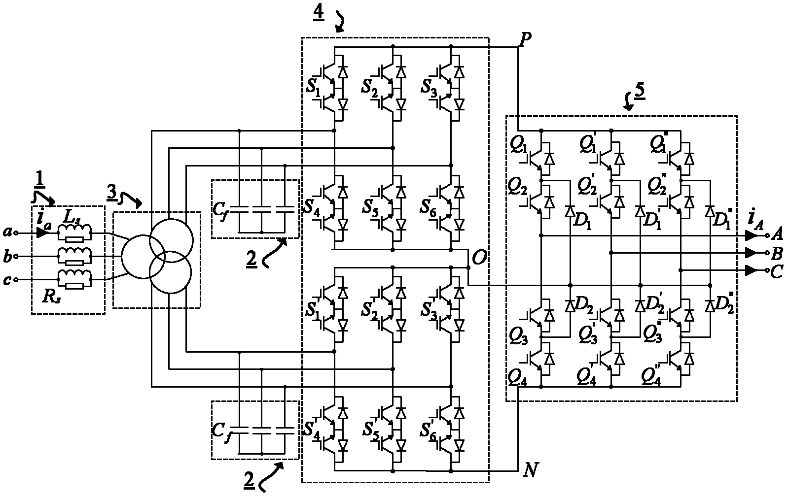
[0057] reference Image 6 The topology and control ideas of the present invention are described. Image 6 The main circuit includes filter reactance and damping resistance 1 , Filter capacitor 2 , Three-phase three-winding transformer 3 , High voltage rectifier 4 , Three-phase diode clamped three-level inverter 5 And drive circuit 8 A total of six parts, the control circuit consists of the sampling circuit 6 And controller 7 composition. Filter reactance and damping resistance 1 The left ends of a, b, and c are respectively connected to the three phases of the three-phase grid, and the right end is connected to the three-phase three-winding transformer 3 The original winding is connected. Three-phase three-winding transformer 3 Two sets of secondary windings and filter capacitors 2 Parallel connection, and then separately with the high voltage rectifier 4 The AC input sides of the two sets of three-phase matrix rectifiers are connected, and the configuration of the two secondary ...


PUM


Abstract

The invention discloses a diode clamped three-level high-voltage matrix converter and a modulation method thereof. The diode clamped three-level high-voltage matrix converter is a novel high-voltage matrix converter formed by connection of two three-phase bi-directional matrix rectifying modules which are in series connection with one diode clamped three-level inverting module. The matrix converter has the advantages of bidirectional flow of energy, sinusoidal input current, controllable power factors, compact structure, output current of good quality, no requirement for a step of direct current energy storage, strong fault-tolerant capability, and the like, and is particularly suitable for medium high-voltage motor drive and a grid-tied wind power generation system.

Description

Technical field [0001] The invention relates to a diode-clamped three-level high-voltage matrix converter and a modulation method thereof, belonging to the field of power electronic technical equipment, and suitable for high-voltage and high-power applications. Background technique [0002] In the context of the world energy crisis, the competent government departments have listed the energy-saving of AC motor speed control systems using frequency converters as a major measure to implement the national energy development policy. The input end of the traditional PWM frequency converter is a three-phase uncontrollable rectifier bridge, and electrolytic capacitors with DC energy storage are needed in the middle, which have the disadvantages of low power factor at the input end, serious harmonic pollution and energy failure. In recent years, with the rapid popularization of traditional PWM inverters, its negative impact on peripheral equipment has become increasingly exposed. Theref...

Claims


Application Information

Patent Timeline
IPC IPC(8): H02M5/458H02P27/06H02J3/38
CPCY02E10/763Y02E10/76
Inventor 孙尧粟梅李幸王辉杨建彭涛于晶荣
Owner CENT SOUTH UNIV
Learn More