
Fine dimming device and dimming control method for light emitting diode (LED) module

A technology of LED modules and dimming devices, applied in the field of stage lighting, can solve problems such as uncomfortable noise, field effect tube switching frequency within the audio frequency range, field effect tube on-off time is difficult to meet the demand, etc., to achieve guaranteed The effect of fineness

Inactive Publication Date: 2014-05-14
佑图物理应用科技发展(武汉)有限公司
View PDF5 Cites 0 Cited by
  • Summary
  • Abstract
  • Description
  • Claims
  • Application Information

AI Technical Summary

Problems solved by technology

When the resolution of the PWM signal is increased, the on-off time of the field effect transistor is difficult to meet the demand.
Moreover, when the frequency of the PWM signal is low, the switching frequency of the FET will be within the audio range
In the application environment of the performance stage, this phenomenon will produce uncomfortable noise, which cannot meet the application requirements in specific environments.

Method used


Image

  • Fine dimming device and dimming control method for light emitting diode (LED) module
  • Fine dimming device and dimming control method for light emitting diode (LED) module

Examples


Embodiment Construction

[0019] Below in conjunction with accompanying drawing and embodiment the present invention is described in further detail:

[0020] Such as figure 1 The shown LED module fine-tuning device includes an LED module and a CPU with a PWM signal output interface, and is characterized in that it also includes a first field effect transistor, a second field effect transistor and a current limiting module, wherein, The first PWM signal output interface of the CPU is connected to the signal input end of the first FET, the signal output end of the first FET is connected to the control end of the LED module through the current limiting module, and the second PWM signal of the CPU The output interface is connected to the signal input end of the second field effect transistor, and the signal output end of the second effect transistor is connected to the control end of the LED module.

[0021] The current limiting module is a current limiting resistor or an inductance coil.

[0022] The di...


PUM


Abstract

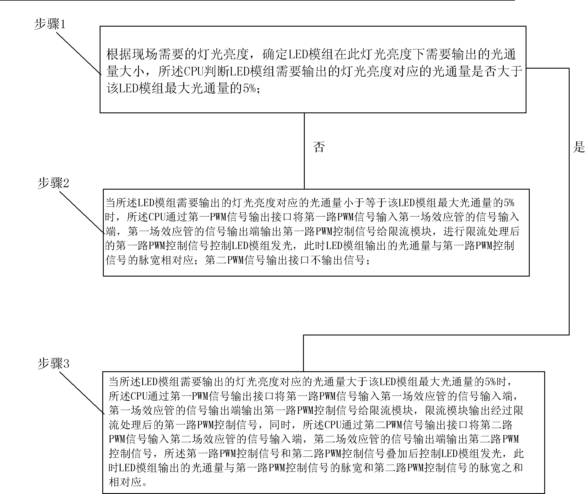
The invention discloses a fine dimming device for a light emitting diode (LED) module. According to the device, a first pulse width modulation (PWM) signal output interface of the central processing unit (CPU) is connected with a signal input end of a first field-effect transistor; a signal output end of the first field-effect transistor is connected with a control end of the LED module through a current-limiting module; a second PWM signal output interface of the CPU is connected with a signal input end of a second field-effect transistor; and a signal output end of the second field-effect transistor is connected with the control end of the LED module. A dimming method comprises the following steps of: 1, judging whether luminosity corresponding to the light illumination which is required to be output by the LED module is greater than 5 percent of the maximum luminosity of the LED module; 2, if the luminosity is not greater than 5 percent of the maximum luminosity of the LED module, controlling the LED module to illuminate through a first PWM control signal by the CPU; and 3, if the luminosity is greater than 5 percent of the maximum luminosity of the LED module, controlling the LED module to illuminate after the first PWM control signal and the second PWM control signal which are sent by the CPU are superposed. According to the method, the ratio of the minimum illumination output to the maximum illumination output exceeds 1:10,000, so the dimming fineness of the LED module is guaranteed.

Description

technical field [0001] The invention relates to the technical field of stage lighting, in particular to an LED module fine dimming device and a dimming control method. technical background [0002] At present, the dimming method of high-power LED (Light Emitting Diode, light-emitting diode) module generally adopts PWM (Pulse Width Modulation, pulse width modulation) signal to control a field effect tube, and then the field effect tube drives the LED module to realize dimming. Light. Compared with traditional tungsten filament lamps, due to the fast reflection speed of LEDs, when the resolution of the PWM signal is low, it can be clearly felt that the dimming process of the LEDs has a gradual jump. When the resolution of the PWM signal is increased, the problem that the turn-on and turn-off time of the field effect transistor cannot meet the requirement exists again. Moreover, when the frequency of the PWM signal is low, the switching frequency of the FET will be within the...

Claims


Application Information

Patent Timeline
Patent Type & Authority Patents(China)
IPC IPC(8): H05B37/02
Inventor 黄振声陈建国段永顺
Owner 佑图物理应用科技发展(武汉)有限公司
Learn More