
Rotary abrasive flow polishing device for integral impeller type parts

A technology of integral impeller and polishing device, applied in the direction of grinding workpiece supports, can solve the problems of local over-polishing, low processing efficiency, difficult-to-process materials, etc., achieve uniform pressure field distribution, solve cleaning problems, and environmental protection of the processing environment.

Active Publication Date: 2012-07-25
DALIAN UNIV OF TECH
View PDF4 Cites 31 Cited by
  • Summary
  • Abstract
  • Description
  • Claims
  • Application Information

AI Technical Summary

Problems solved by technology

At present, enterprises mainly use manual polishing process. It takes a long time to polish a part, and the polishing texture is chaotic and irregular, which leads to high labor intensity and serious environmental pollution.
The main difficulties in the processing of such parts are: (1) the parts to be processed are mostly complex curved surface structures; (2) the materials to be processed are mostly high-temperature alloys, titanium alloys, stainless steel and other difficult-to-machine materials; (3) the surface roughness of the processing The requirements are high, and the surface roughness after polishing should be below Ra 0.8
[0003] The use of abrasive flow technology to polish the surface of special-shaped inner cavity parts such as pipes is a good process method. However, the current abrasive flow technology mainly uses single-pass polishing for complex parts such as integral impellers, blisks and other rotary parts. Single-out one-way abrasive flow processing method; for the polishing of simple parts, such as pipes, bearing rings, cylinders and other smooth inner wall surfaces, repeated polishing can be achieved, mainly because the parts are simple, the fluid control is convenient, and The fluid can flow through the inner wall surface evenly, but for parts with complex surfaces, the pressure field in the polishing area is not uniform due to the difficulty of controlling the fluid abrasive and the inhomogeneity of the abrasive flow into the flow channel of each blade (cascade). , which in turn leads to uneven processing quality or local over-polishing. For the one-way abrasive flow processing method with one-in and one-out, the abrasive is not easy to recycle, the processing efficiency is low, and the surface of the part after polishing needs to be cleaned.

Method used


Image

  • Rotary abrasive flow polishing device for integral impeller type parts
  • Rotary abrasive flow polishing device for integral impeller type parts
  • Rotary abrasive flow polishing device for integral impeller type parts

Examples


Embodiment Construction

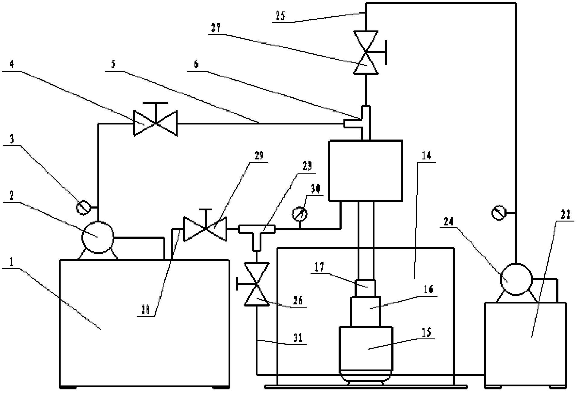
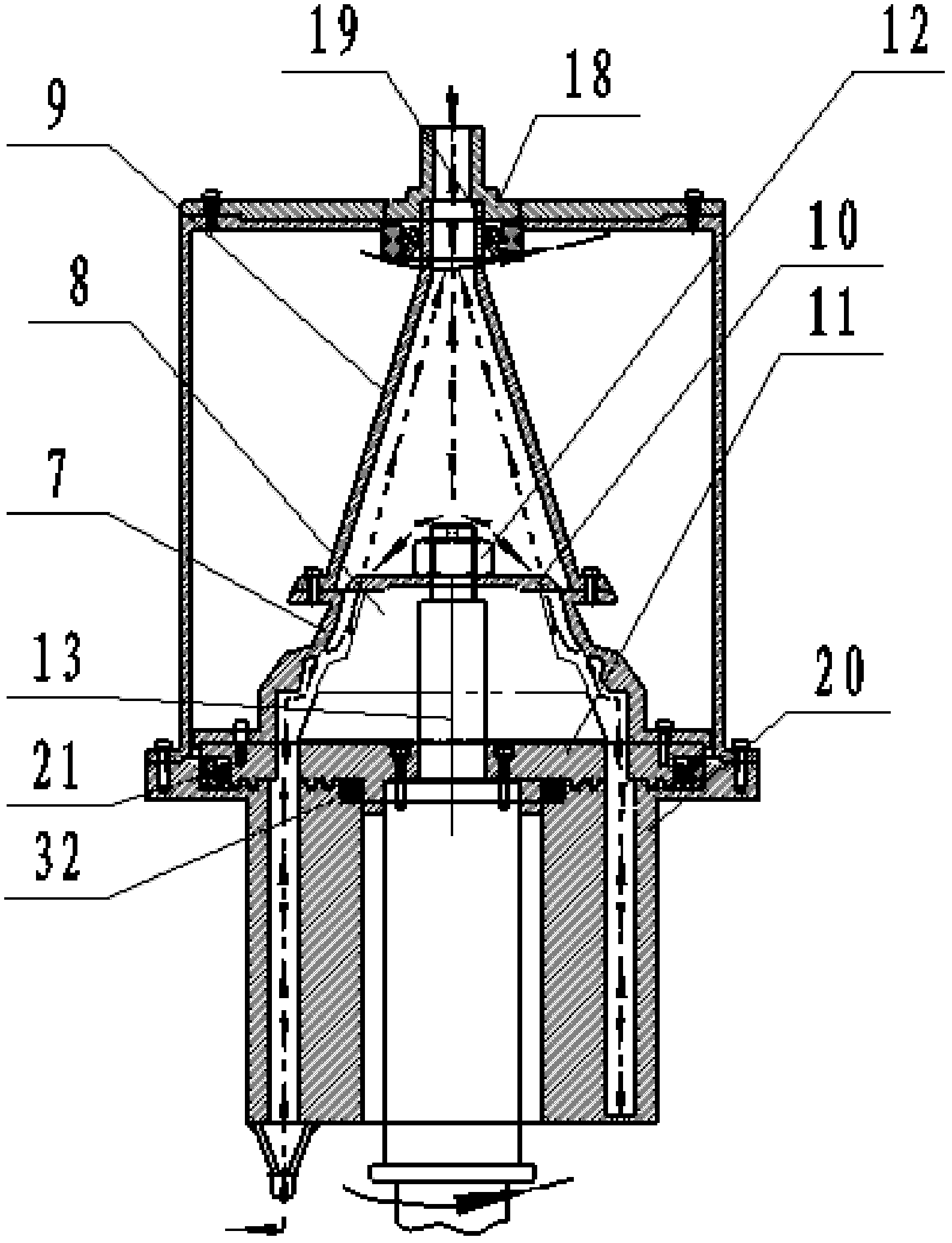
[0037] The following takes the integral radial flow titanium alloy impeller as an example, refer to the attached figure 1 , with figure 2 The implementation process of the rotary abrasive flow polishing device and method is described:

[0038] The integral radial flow titanium alloy impeller abrasive flow device includes the following structure:

[0039] Firstly, the main body 7 of the profiled jig cover 7 which is similar to the shape of the overall impeller curve is covered on the blades of the overall impeller, and is fixed integrally with the overall impeller 8 through the upper and lower jig covers 10 and 11 .

[0040] Secondly, the integral impeller 8, the fixture cover main body 7, and the upper and lower furniture covers 10, 11 are fixed on the machine tool spindle 13 by the round nut 12, and the machine tool spindle 13 is fixed on the workbench shaft seat 14, and the reducer is driven by the motor 15 16 is connected to the main shaft 8 through the reducer connectin...


PUM


Abstract

A rotary abrasive flow polishing device for integral impeller type parts comprises a feeding system, a spindle system, a device body, a clamp cover, a guide structure and a cleaning system, wherein the feeding system is used for regular bidirectional feeding and controlling abrasive flow, the spindle system is capable of rotating positively and reversely and adjustable in rotation speed, the clamp cover clamps an impeller to form a closed cavity and protects non-polishing sides and upper and lower edges, the guide structure is used for guiding abrasives, and the cleaning system is used for realizing cleanness in ingoing and outgoing. The rotary abrasive flow polishing device solves the problems of easiness in interference, over-polishing of blades, chamfering, dead angles and nonuniform polishing in polishing of integral impeller type parts, the abrasives can bidirectioally cyclically flow to be recovered easily, machining efficiency is improved, and cleanness in ingoing and outgoing during machining can be realized by means of the cleaning system used after polishing is completed.

Description

technical field [0001] The invention relates to a rotary abrasive flow polishing device for integral impeller parts. Background technique [0002] Rotary parts such as integral impellers and blisks in mechanical products such as aero-engines and compressors need to be polished to achieve the low-roughness and smooth surface processing requirements of the blade (cascade) surface after milling or electrolytic machining. At present, enterprises mainly use manual polishing process, which takes a long time to polish a part, and the polishing texture is chaotic and irregular, which results in high labor intensity and serious environmental pollution. The main difficulties in the processing of such parts are: (1) the parts to be processed are mostly complex curved surface structures; (2) the materials to be processed are mostly high-temperature alloys, titanium alloys, stainless steel and other difficult-to-machine materials; (3) the surface roughness of the processing The requirem...

Claims


Application Information

Patent Timeline
IPC IPC(8): B24B1/00B24B41/06
Inventor 高航孙玉文吴鸣宇郭东明
Owner DALIAN UNIV OF TECH
Learn More