

Reusable packing tackle
A locking plate, movable fixing technology, applied in packaging, packaging recycling, transportation and packaging, etc.
- Summary
- Abstract
- Description
- Claims
- Application Information
AI Technical Summary
Problems solved by technology
Method used
Image

Examples
Embodiment 1
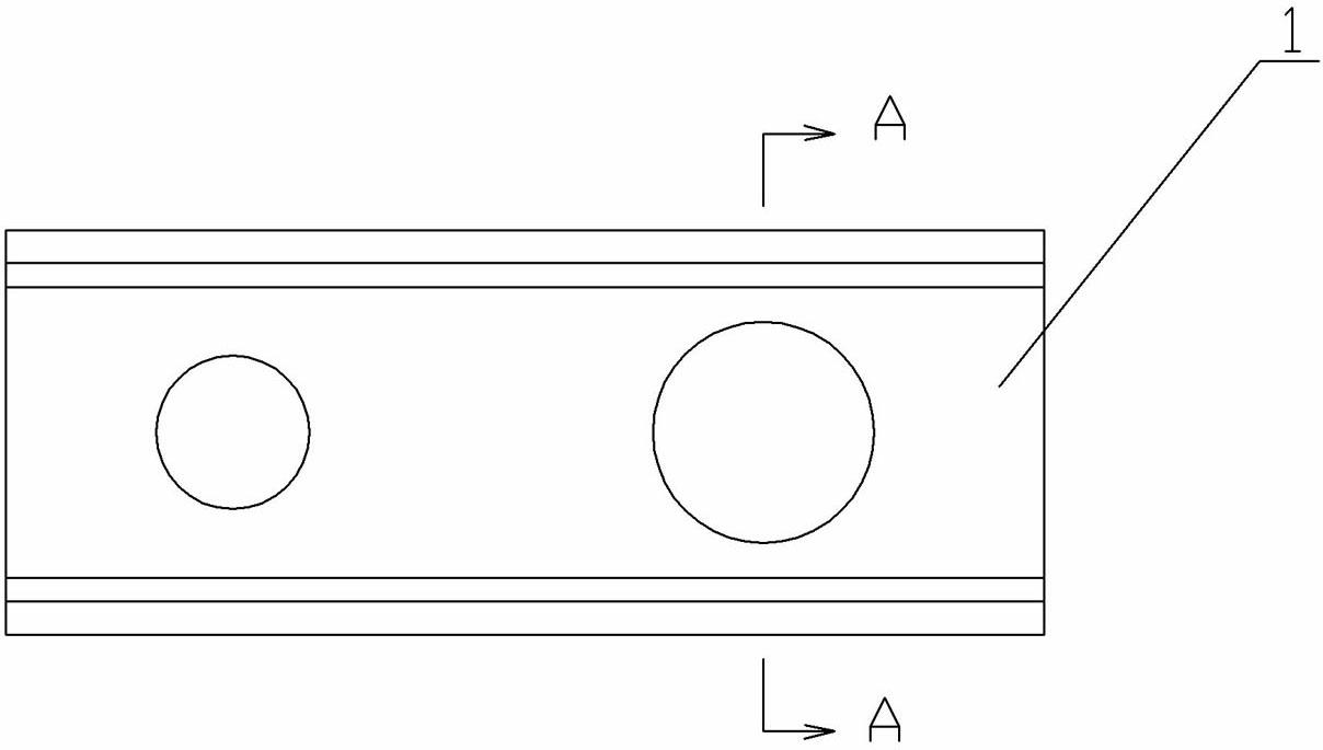
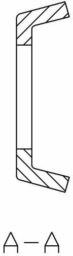
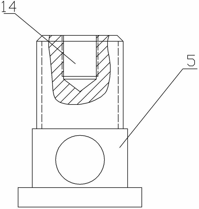
[0042] see Figure 1-Figure 5 : 1-lock plate, 2-wing nut, 3-cover nut, 4-lock screw, 5-telescopic screw, 6-lock cover screw, 7-cable concrete, 8-movable fixed head, 9-large flat washer Sheet, 10-small flat gasket, 11-big spring pad, 12-small spring pad, 13-spindle body end, 14-threaded blind hole.
[0043] Cable concrete 7 is steel wire rope.
[0044] Two holes of different sizes are arranged at both ends of the locking plate 1, and the locking screw 4 and the telescopic screw 5 pass through the two holes respectively, and the lower ends of the locking screw 4 and the telescopic screw 5 are each provided with a through hole, and the cable specifically One end of 7 is inserted in the through hole of locking screw rod 4, and cover nut 3 cooperates with locking screw rod 4 to lock cable concrete 7 dead, and butterfly nut 2 cooperates with telescopic screw rod 5, and telescopic screw rod 5 upper end has screw thread blind hole 14, prevents Loose cover screw 6 cooperates with thr...
Embodiment 2
[0050] see Figure 6-Figure 7 : 1-lock plate, 7-cable concrete, 8-movable fixed head, 15-T-shaped card slot.
[0051] Cable concrete 7 is steel wire rope.
[0052] One end of the cable concrete 7 is riveted and fixed on one end of the lock plate 1, and the lock plate 1 is provided with a T-shaped card slot 15, and the movable fixed head 8 tail of the other end of the cable concrete 7 has a blind hole, and the cable concrete 7 is inserted into the blind hole. Apply high pressure with a mold behind the hole, so that the pipe wall of the tail hole of the movable fixed head 8 and the cable body 7 produce permanent plastic deformation, so as not to be pulled apart by a strong elastic force.
[0053] The shape of the movable fixed head 8 is approximately an inverted L shape.
[0054] The length of the shorter vertical bar of the movable fixed head 8 is slightly greater than the length of the T-shaped draw-in groove 15 positioned at half of the groove body in the cross-sectional di...
Embodiment 3
[0057] see Figure 8-Figure 9 : 1-lock plate, 7-cable concrete, 8-movable fixed head, 16-blunt head, 17-nut.
[0058] The cross section of the locking plate 1 is groove-shaped.
[0059] Both ends of the locking plate 1 are provided with baffles in the cross-sectional direction, and holes are provided on the baffles.
[0060] Cable concrete 7 is steel wire.
[0061] One end of the cable concrete 7 is welded and fixed with the blunt head 16 hinged in the baffle hole, and the other end of the cable concrete 7 is welded and fixed with the threaded cylindrical movable fixed head 8 one end. The other end of the movable fixed head 8 penetrates into the baffle plate hole at the other end of the strike plate 1 , and the penetration end is fixed with the nut 17 .
PUM
 Abstract
Description
Claims
Application Information