
Composite phase-change heat exchange system

A technology of composite phase-change heat and phase-change heat exchanger, which is applied in the field of composite phase-change heat systems, can solve the problems of large amount of consumables, complex structure, low-temperature corrosion resistance, etc., and achieves small steel consumption, simple structure, good promotional effect

Inactive Publication Date: 2012-07-25
长春当代信息产业集团有限公司
View PDF8 Cites 19 Cited by
  • Summary
  • Abstract
  • Description
  • Claims
  • Application Information

AI Technical Summary

Problems solved by technology

[0005] In view of the above-mentioned deficiencies in the prior art, the purpose of the present invention is to provide a composite phase-change heat system, which aims to solve the problems of low-temperature corrosion resistance, ash blocking resistance, complex structure, and large amount of consumables that exist in the recovery of waste heat from boiler flue gas. The contradiction between disadvantages and economy

Method used


Image

  • Composite phase-change heat exchange system
  • Composite phase-change heat exchange system

Examples


Embodiment Construction

[0019] The present invention provides a composite phase change heat system. In order to make the purpose, technical solution and effect of the present invention clearer and clearer, the present invention will be further described in detail below. It should be understood that the specific embodiments described here are only used to explain the present invention, not to limit the present invention.

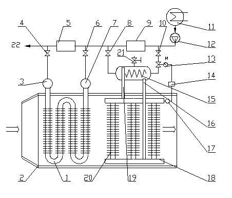
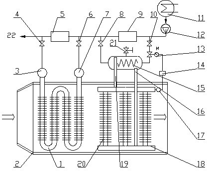
[0020] see figure 1 , figure 1 It is a structural schematic diagram of a specific embodiment of a composite phase-change heat system of the present invention, such as figure 1 As shown, it includes: single-phase heat exchanger 1, flue 2, left header 3, first valve 4, first low-pressure heater 5, second valve 6, right header 7, third valve 8, second Low pressure heater 9, fourth valve 10, condenser 11, condensate pump 12, electric control valve 13, temperature controller 14, upper section of vacuum phase change heat exchanger 15, condensate pipe 16, temperature sensor 17, vacuum ph...


PUM


Abstract

The invention discloses a composite phase-change heat exchange system for afterheat recovery of exhaust gas at the tail part of a boiler. The composite phase-change heat exchange system comprises a single-phase heat exchanger and a vacuum phase-change heat exchanger, which are sequentially connected, and afterheat recovery of the exhaust gas is achieved by the exhaust gas at the tail part of the boiler through the single-phase heat exchanger and the vacuum phase-change heat exchanger. The composite phase-change heat exchange system disclosed by the invention not only has the advantages of being simple in structure, small in steel dosage and economic and safe in operation of the single-phase heat exchanger, but also has the advantages of being corrosion-resistant, anti-clogging, energy-saving and the like at the same time. The composite phase-change heat exchange system also has economic and practical significances and good popularization while being suitable for afterheat recovery of low-temperature exhaust gas under the current situations of saving energy and reducing emission.

Description

technical field [0001] The invention relates to the field of heat exchange systems, in particular to a composite phase-change heat system mainly used for boiler flue gas waste heat recovery. Background technique [0002] In boiler flue gas waste heat recovery, it is generally used to install a heating surface at the rear to improve the thermal efficiency of thermal equipment. The use of flue gas waste heat heating is a widely used method. There are also conventional heat exchangers used in coal-fired, oil-fired boilers or low-temperature flue gas waste heat recovery of industrial furnaces, but their lifespan is very short, and they will even be scrapped in a few months. Because coal and fuel oil contain sulfur, the sulfur in the fuel will produce sulfur dioxide after combustion, and a part of the sulfur dioxide will react with the oxygen in the combustion products to form sulfur trioxide. When the sulfur trioxide combines with the water vapor in the flue gas and This will ...

Claims


Application Information

Patent Timeline
Patent Type & Authority Applications(China)
IPC IPC(8): F22D1/00F28F27/00
CPCY02P10/25Y02P80/15
Inventor 苏俊林胡光
Owner 长春当代信息产业集团有限公司
Learn More