
Signal conditioning circuit of ACFM (Alternating Current Field Measurement) digital detector

A signal conditioning circuit and detector technology, applied in the direction of material magnetic variables, etc., can solve the problems of low measurement accuracy, single measurement type, and inability to digital control, etc., achieve high detection accuracy, stable and reliable work, and overcome poor applicability.

Inactive Publication Date: 2012-07-25
NANCHANG HANGKONG UNIVERSITY
View PDF5 Cites 6 Cited by
  • Summary
  • Abstract
  • Description
  • Claims
  • Application Information

AI Technical Summary

Problems solved by technology

[0009] The technical effect of the present invention is: it overcomes the disadvantages of the current ACFM signal conditioning circuit, such as poor applicability, single measurement type, low measurement accuracy and incapable of digital control, and has the characteristics of wide application range, high detection accuracy, digital controllability, stable and reliable operation , can be used in the signal conditioning circuit of cost-effective ACFM detection instrument

Method used


Image

  • Signal conditioning circuit of ACFM (Alternating Current Field Measurement) digital detector
  • Signal conditioning circuit of ACFM (Alternating Current Field Measurement) digital detector
  • Signal conditioning circuit of ACFM (Alternating Current Field Measurement) digital detector

Examples


Embodiment Construction

[0012] The present invention will be described in detail below with reference to the drawings and specific embodiments.

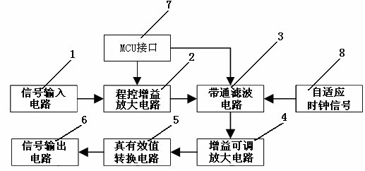
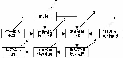
[0013] Such as figure 1 As shown, the present invention includes a signal input circuit 1, a programmable gain amplifier circuit 2, a band-pass filter circuit 3, a gain adjustable amplifier circuit 4, a true effective value conversion circuit 5, a signal output circuit 6, an MCU interface 7 and an adaptive clock signal 8. The feature is that the signal input circuit 1 is connected to the programmable gain amplifier circuit 2, the programmable gain amplifier circuit 2 is connected to the band-pass filter circuit 3, the band-pass filter circuit 3 is connected to the gain adjustable amplifier circuit 4, and the gain adjustable amplifier circuit 4 is connected really effectively The value conversion circuit 5, the true effective value conversion circuit are connected to the signal output circuit 6, the MCU interface 7 is connected to the programmable gain amplifier...


PUM


Abstract

The invention provides a signal conditioning circuit of an ACFM (Alternating Current Field Measurement) digital detector, comprising a signal input circuit, a program control gain amplification circuit, a band-pass filtering circuit, a gain adjustable amplification circuit, a true effective value conversion circuit, a signal output circuit, an MCU (Micro-programmed Control Unit) interface and a self-adapting clock signal. The signal conditioning circuit is characterized in that: the signal input circuit is connected with the program control gain amplification circuit; the program control gain amplification circuit is connected with the band-pass filtering circuit; the band-pass filtering circuit is connected with the gain adjustable amplification circuit; the gain adjustable amplification circuit is connected with the true effective value conversion circuit; the true effective value conversion circuit is connected with the signal output circuit; the MCU interface is connected with the program control gain amplification circuit and the band-pass filtering circuit; and the self-adapting clock signal is connected with the band-pass filtering circuit. The signal conditioning circuit has the technical effects that: the defects that the applicability of the existing ACFM signal conditioning circuit is poor, the measurement type is single, the measurement precision is not high and the digital control cannot be realized are overcome; the signal conditioning circuit has the characteristics of wide applicable range, high detection precision, digital controllability and stable and reliable work, and can be applied to the signal conditioning circuit of the ACFM digital detector with the high cost performance.

Description

Technical field [0001] The invention relates to a signal conditioning circuit, in particular to a signal conditioning circuit of an ACFM digital detector. Background technique [0002] In recent years, based on eddy current testing and magnetic flux leakage testing, a new non-destructive testing technology has been developed-Alternating Current Field Measurement (ACFM). This technology uses conductive materials under the action of alternating current, and the defects and cracks of the material will change the distribution of the induced current around it, thereby changing the distribution of the induced magnetic field on the surface of the ferromagnetic test piece. By measuring the change of the induced magnetic field on the surface, and according to the inversion of the mathematical model, the length and depth of the crack defect are determined. [0003] During the use of ferromagnetic components, under the action of stress corrosion, fatigue load, internal working medium or exte...

Claims


Application Information

Patent Timeline
Patent Type & Authority Applications(China)
IPC IPC(8): G01N27/82
Inventor 任尚坤李兵
Owner NANCHANG HANGKONG UNIVERSITY
Learn More