Monocrystalline welding of directionally compacted materials

A technology of directional crystallization and crystallization, which is applied in the growth of polycrystalline materials, welding media, single crystal growth, etc., and can solve problems such as wrong orientation

Inactive Publication Date: 2012-07-25
SIEMENS AG +1
View PDF13 Cites 4 Cited by
  • Summary
  • Abstract
  • Description
  • Claims
  • Application Information

AI Technical Summary

Problems solved by technology

The cause of misorientation in the SX microstructure during powder overlay welding of γ'-strengthened SX Ni-based superalloys is not yet fully understood

Method used


Image

  • Monocrystalline welding of directionally compacted materials
  • Monocrystalline welding of directionally compacted materials
  • Monocrystalline welding of directionally compacted materials

Examples


Embodiment Construction

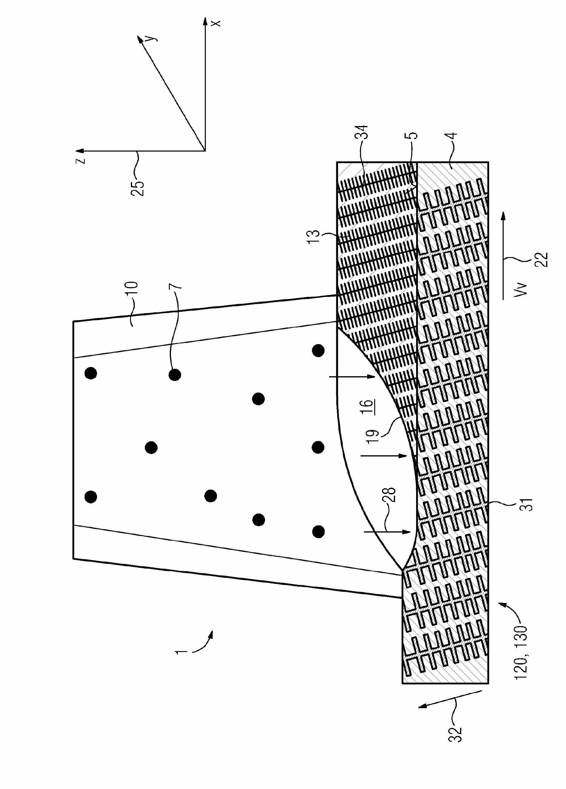
[0014] exist figure 1 The flow of the method is shown schematically with the aid of device 1 .

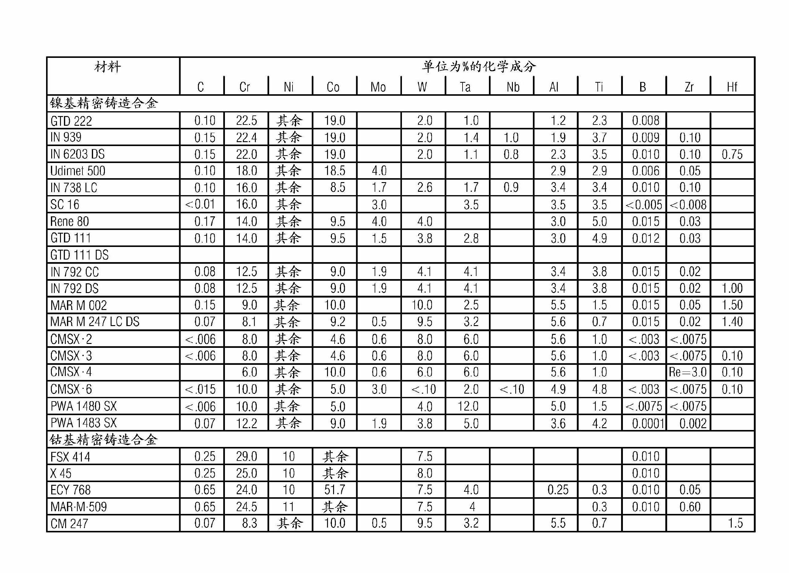
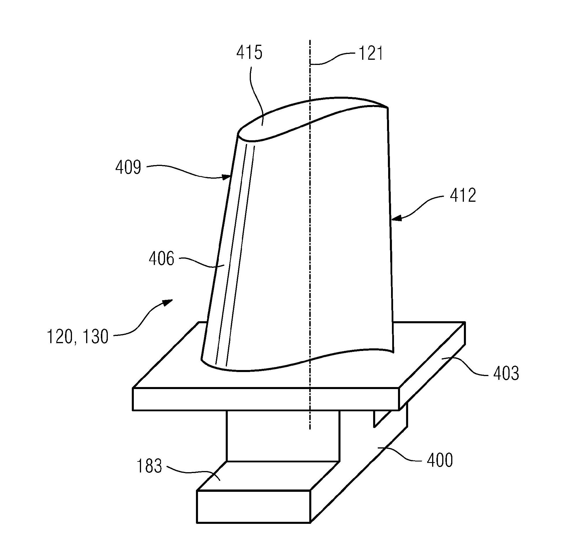
[0015] Components 120, 130 to be repaired have properties made of superalloys, in particular according to Figure 4 A substrate made of a nickel-based superalloy 4 . The substrate 4 is in particular entirely made of a nickel-based superalloy. The substrate 4 is repaired by applying new material 7 to the surface 5 of the substrate 4 by overlay welding, in particular by means of powder.

[0016] This is achieved by supply material 7 and a welding beam, preferably a laser beam 10 of a laser, which melts at least the supplied material 7 and preferably also partially melts the substrate 4 . Here, powders are preferably used. The diameter of the powder particles 7 is preferably so small that the laser beam completely melts them and achieves a sufficiently high temperature of the particles 7 . During welding, there is a melted region 16 on the substrate 4 , a solidification front 19 ...


PUM

PropertyMeasurementUnit
diameteraaaaaaaaaa

Abstract

The invention relates to a method for directionally compacting a weld seam (13) during build-up welding, in particular for the build-up welding of a substrate (4) of a component (1) that is compacted in a directional manner and comprises dendrites (31), which extend in a substrate dendrite direction (32), wherein the method parameters with respect to feed, laser power, weld beam diameter, powder beam focus and / or powder mass flow are designed such that said parameters result in a local orientation of the temperature gradient (28) to the solidification front (19), which is smaller than 45 with respect to the substrate dendrite direction (32) of the dendrites (31) in the substrate (4), wherein the relative speed is between 30 mm / mm and 100 mm / mm, preferably 50 mm / mm, and / or the power is between 200 W and 500 W, preferably 300 W, and / or the diameter of the laser beam on the surface of the substrate is between 3 mm and 6 mm, preferably 4 mm, and / or the mass feed rate is between 300 mg / mm and 600 mg / mm, preferably 400 mg / m..

Description

technical field [0001] The invention relates to a welding method of directional crystallized metal materials. Background technique [0002] γ’-strengthened SX nickel-based superalloys cannot be overlay-welded in one or more layers with filler materials of the same type in overlapping welding trajectories, neither by conventional welding methods nor by high-energy methods (laser, electron beam). The problem is that, in the case of individual welding tracks in the edge region close to the surface, an incorrectly oriented tissue has formed. For successive overlapping tracks, this means that the solidification front in this region has no SX nuclei and that the region continues to expand in the overlapping region with a wrong orientation (no SX structure). Cracks form in this area. [0003] For γ'-strengthened SX nickel-based superalloys, the welding methods used so far do not allow the weld metal to be constructed homogeneously in one or more layers with the same SX structure ...

Claims


Application Information

Patent Timeline
Patent Type & Authority Applications(China)
IPC IPC(8): B23K26/34C30B13/24
CPCC30B29/52C30B11/005B23K2201/001B23K26/3213C30B13/22B23K26/345B23K26/3206B23K26/34B22F2007/068B23K26/32B23K35/0244B23K35/3033B23K26/342B23K2101/001B23K2103/08B23K2103/26B23K2103/50C22C19/058C22C19/07F05D2230/313F05D2300/606
Inventor 贝恩德·布尔鲍姆安德烈斯·加塞尔托尔斯滕·扬博尔斯特法尼·林嫩布林克诺贝特·皮尔沙尼古拉·阿里亚金乔治·博斯坦约格洛托尔斯滕·梅尔策-约基施塞利姆·莫卡德姆米夏埃尔·奥特罗尔夫·维尔肯赫纳
Owner SIEMENS AG
Why Eureka
Try Eureka