Speed sensor installation structure in a vehicle

A vehicle speed sensor and vehicle technology, which is applied in the direction of bicycle sensor, vehicle components, cooling combination of power plant, etc., to achieve the effect of preventing water splashing

Active Publication Date: 2012-07-25
HONDA MOTOR CO LTD
View PDF6 Cites 0 Cited by
  • Summary
  • Abstract
  • Description
  • Claims
  • Application Information

AI Technical Summary

Problems solved by technology

[0005] However, in the content described in the above-mentioned Patent Document 1, the pick-up is installed on the rear portion of the swing arm in a manner extending in the radial direction of the final drive gear. The protective cover that covers the pick-up, and when the pick-up is arranged in the swing arm, it is necessary to secure a space for arranging the pick-up in the length direction of the swing arm, so the swing arm is extended in the front-rear direction

Method used


Image

  • Speed sensor installation structure in a vehicle
  • Speed sensor installation structure in a vehicle
  • Speed sensor installation structure in a vehicle

Examples


Embodiment 1

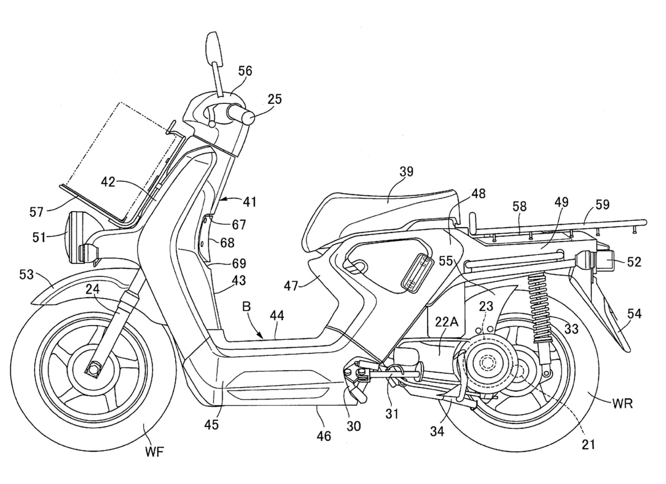
[0048] refer to Figure 1~Figure 5 Embodiment 1 of the present invention is described, at first in figure 1 Among them, the electric two-wheeled vehicle is a scooter-type electric two-wheeled vehicle having a low pedal 44, and the electric two-wheeled vehicle is configured such that the electric motor 23 as a power source built in the rocker arm 22A outputs rotational power to drive the electric two-wheeled vehicle. The rear wheel WR rotates, and the swing arm 22A pivotally supports the axle shaft 21 of the rear wheel WR at the rear.

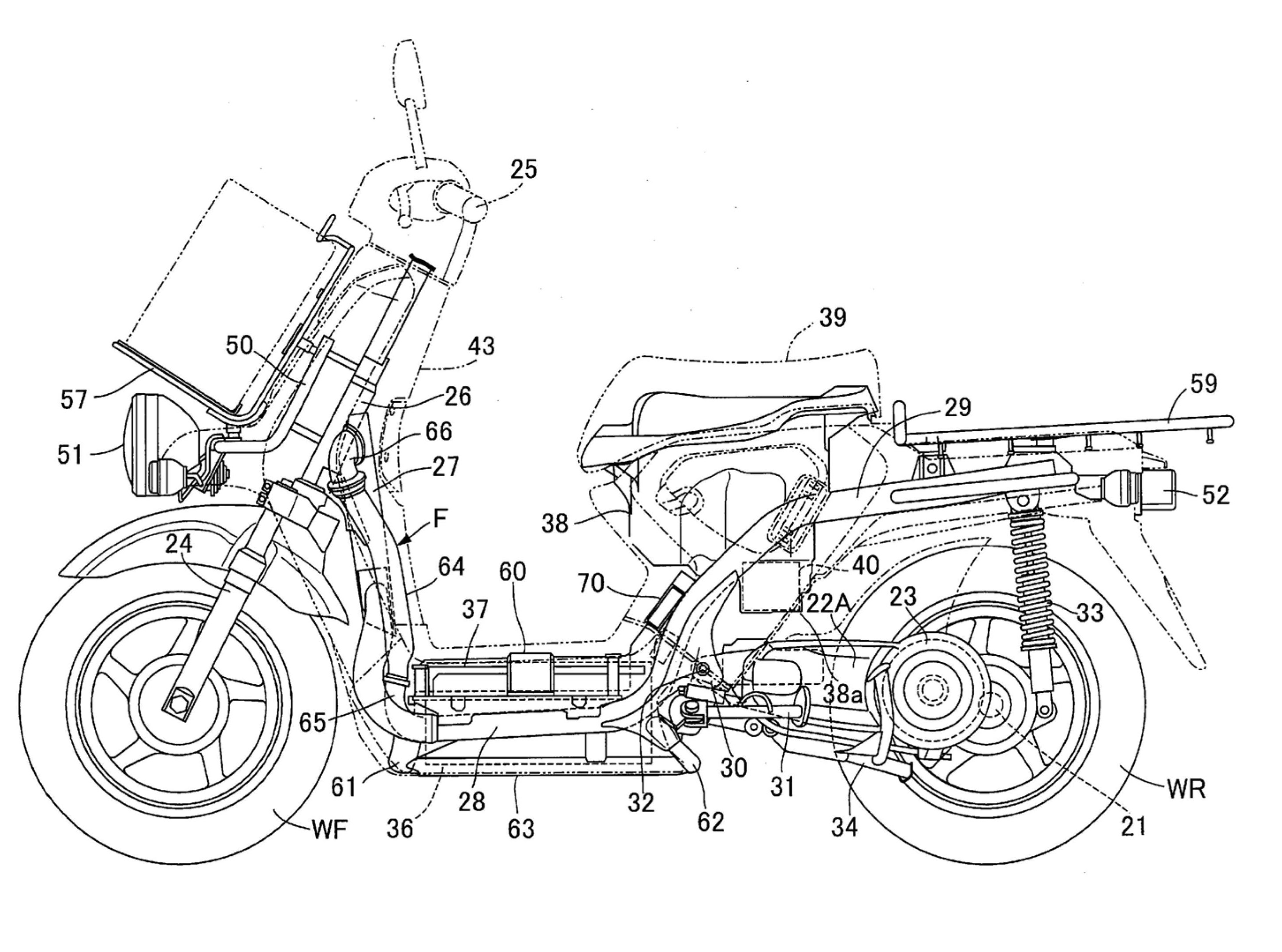
[0049] exist figure 2 Among them, the frame F of the electric two-wheeled vehicle is provided with: a head pipe 26 that can steerably support a front fork 24 that pivotally supports the front wheel WF and a steering handle 25 connected to the upper part of the front fork 24; The lower frame 27 extending backward and downward; the left and right pair of lower frames 28 connected to the bottom of the lower frame 27 and extending backward; To r...

Embodiment 2

[0075] refer to Image 6 Embodiment 2 of the present invention will be described, and parts corresponding to the above-mentioned Embodiment 1 will be denoted by the same reference numerals, and detailed description will be omitted.

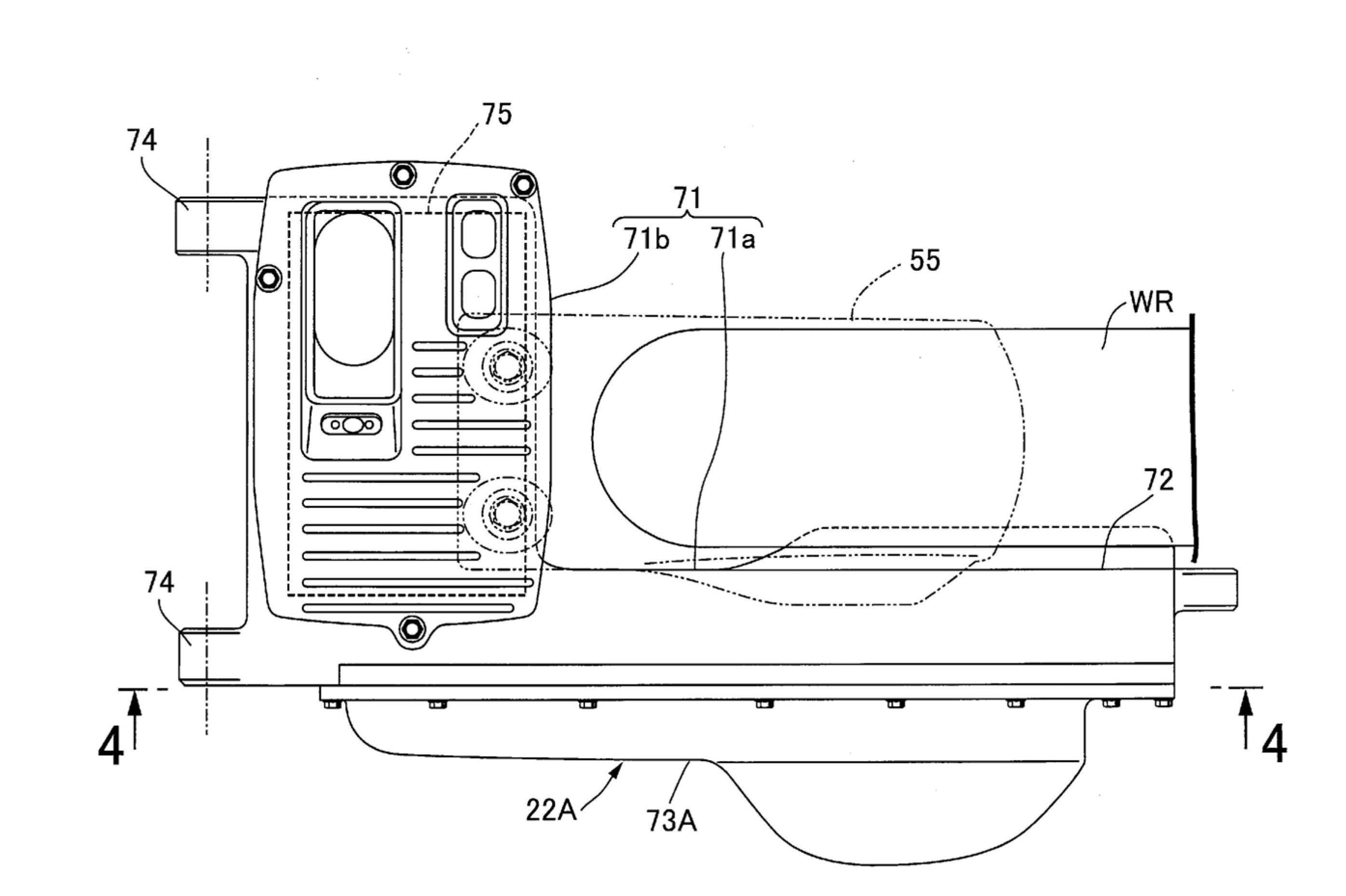
[0076] The swing arm 22B is coupled to the swing arm main body 71 from the left side (outer side) by the swing arm main body 71 and the gear case 72 coupled to the rear part of the arm portion 71 a of the swing arm main body 71 from the rear wheel WR (refer to Example 1) side. The rear part of the rocker arm 22B pivotally supports the axle 21 of the rear wheel WR, and accommodates the electric motor 23 and the power transmission device 77 including the reduction gear set 78 and the centrifugal clutch 79 .

[0077] On one of the two axial end faces of the final drive gear 103 of the reduction gear set 78, in the first embodiment, on the end face on the opposite side to the rear wheel WR, a plurality of positions are provided at equal intervals in t...


PUM


Abstract

A speed sensor installation structure in a vehicle, wherein a power transmitting means for transmitting power from a power source to the axle of a rear wheel is housed in a swing arm which is swingably supported at a vehicle frame, the final gear of a reduction gear train forming a portion of the power transmitting means is fixed to the axle, and a pick-up which forms a speed sensor together with a detected part provided in the final gear is mounted on the swing arm opposite of the detected unit. The detected part (108) is provided at one of the axial end surfaces of the final gear (103), and the pick-up (109) is mounted to the swing arm (22A) so as to extend parallel to the axis of the axle (21). Due to this, even if a pick-up is installed at a swing arm, increases in length of the swing arm in the front and back direction can be prevented, and the structure can be made compact.

Description

technical field [0001] The present invention relates to a vehicle, in particular to an improvement in the arrangement structure of a vehicle speed sensor. In this vehicle, the axle of the rear wheel is pivotally supported at the rear of the rocker arm which is swingably supported on the vehicle frame, and the power from the power source is transmitted. A power transmission device to the axle is accommodated in the rocker arm, a final drive gear of a reduction gear set constituting a part of the power transmission device is fixed to the axle, and a detected portion provided on the final drive gear A pickup that together constitutes a vehicle speed sensor is attached to the swing arm facing the detected portion. Background technique [0002] It has been disclosed in Patent Document 1 that a part of the power transmission device that transmits power from the internal combustion engine and is accommodated in the rocker arm is composed of a reduction gear set having a final drive...

Claims


Application Information

Patent Timeline
Patent Type & Authority Applications(China)
IPC IPC(8): B62J99/00B62K25/20B62M7/12
CPCB62K11/10B60K11/08B62M7/12B62J99/00B60Y2200/12B60K15/05B60K2007/0061B60K1/04B62J2099/002B62J17/06B62K2207/00B60Y2200/126B60K7/0007B60K2001/005B60K2007/0053B62K2204/00B62K2202/00B60L2220/46B62J43/20B62J43/30B62J45/412B62J45/42
Inventor 味村政秀新妻桂一郎
Owner HONDA MOTOR CO LTD
Why Eureka
Try Eureka